ITC 220 Base Station Transceiver Installation Guide PN 133991 Rev. A
| Page 19
6.9
CONNECT THE ETHERNET CABLE
The Base Station Transceiver requires a shielded Category 5 (or better) Ethernet cable with an RJ-45 connector. It is
recommended that the cable length not exceed 100 meters. Insert the RJ-45 connector into the LAN port on the back
of the unit above the GPS antenna connector.
6.10
CONNECT THE POWER CABLE
Warning
– Applying an incorrect voltage to the Base Station Transceiver can cause damage. Confirm the
voltage rating of the Transceiver and power source before applying power.
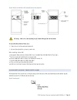
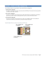
The Base Station Transceiver has two 5/16-inch studs ( and – ) to connect the 10 AWG power cables. The
power connectors are threaded posts for ring lug terminals and are located on the rear panel of the unit.
Figure 11 Power connector studs on the rear panel of the Base Station Transceiver
The power connectors are threaded posts for ring lug terminals and are located on the rear of the unit.
Important!
The transceiver does not have a power switch. Applying power to the threaded posts on the rear panel of
the Base Station Transceiver powers it on. Do not connect the transceiver to power until instructed to do so later in
these instructions. Verify that the power is off before connecting the unit to a power source.
Figure 12, which follows, shows recommended construction of a power cable and the lock washers and nuts required
to connect the power cable to the unit.


