


En-9
3.7. Vacuum process
CAUTION
• Perform a refrigerant leakage test (air tightness test) to check for leaks using nitrogen
gas while all valves in the outdoor unit are closed. (Use the test pressure indicated
on the nameplate.)
• Be sure to evacuate the refrigerant system using a vacuum pump.
• The refrigerant pressure may sometimes not rise when a closed valve is opened after
the system is evacuated using a vacuum pump. This is caused by the closure of the
refrigerant system of the outdoor unit by the electronic expansion valve. This will not
affect the operation of the unit.
• If the system is not evacuated suf
fi
ciently, its performance will drop.
• Use a clean gauge manifold and charging hose that were designed speci
fi
cally for use
with R32(R410A). Using the same vacuum equipment for different refrigerants may
damage the vacuum pump or the unit.
• Do not purge the air with refrigerants, but use a vacuum pump to evacuate the sys-
tem.
Refrigerant for purging the air is not charged in the outdoor unit at the factory.
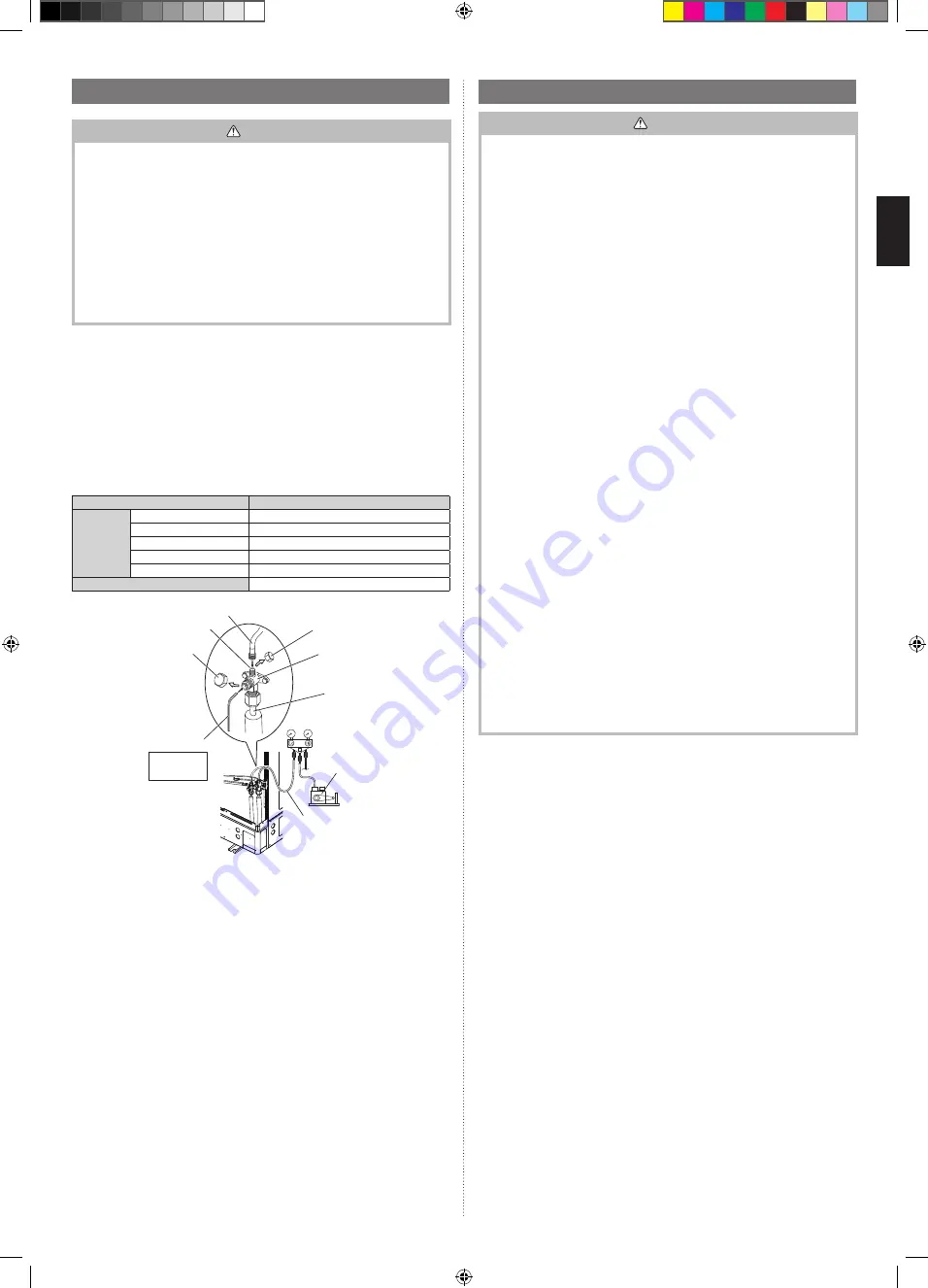
(1) Remove the cap, and connect the gauge manifold and the vacuum pump to the
charging valve by the service hoses.
(2) Vacuum the indoor unit and the connecting pipes until the pressure gauge indicates
–0.1 MPa (–76 cmHg).
(3) When –0.1 MPa (–76 cmHg) is reached, operate the vacuum pump for at least
60 minutes.
(4) Disconnect the service hoses and
fi
t the cap to the charging valve to the speci
fi
ed
torque.
(5) Remove the blank caps, and fully open the spindles of the 3-way valves with a
hexagon wrench [Torque: 6~7 N·m (60 to 70 kgf·cm)].
(6) Tighten the blank caps of the 3-way valves to the speci
fi
ed torque.
Tightening torque
Blank cap
6.35 mm (1/4 in.)
20 to 25 N·m (200 to 250 kgf·cm)
9.52 mm (3/8 in.)
20 to 25 N·m (200 to 250 kgf·cm)
12.70 mm (1/2 in.)
28 to 32 N·m (280 to 320 kgf·cm)
15.88 mm (5/8 in.)
30 to 35 N·m (300 to 350 kgf·cm)
19.05 mm (3/8 in.)
35 to 40 N·m (350 to 400 kgf·cm)
Charging port cap
12.5 to 16 N·m (125 to 160 kgf·cm)
Service hose
Service hose with valve core
Charging port
Blank cap
Hexagon wrench
Connecting pipe
Gauge manifold
Vacuum pump
Charging port cap
3-way valve
Use a 4 mm
hexagon
wrench
3.8. Electrical wiring
WARNING
• Wiring connections must be performed by a quali
fi
ed person in accordance with
the speci
fi
cations. The voltage rating for this product is 230 V at 50 Hz. It should be
operated within the range of 198 to 264 V. The voltage rating for the three-phase
product is 400 V at 50 Hz. It should be operated within the range of 342 to 456 V.
• Before connecting the wires, make sure the power supply is off.
• Never touch electrical components immediately after the power supply has been
turned off. Electrical shock may occur. After turning off the power, always wait
10 minutes or more before touching electrical components.
• Use a dedicated power supply circuit. Insuf
fi
cient power capacity in the electrical
circuit or improper wiring may cause electric shock or
fi
re.
• Be sure to install an earth leakage breaker.
Otherwise, it will cause electric shock or
fi
re.
• A circuit breaker is installed in the permanent wiring. Always use a circuit that can
trip all the poles of the wiring and has an isolation distance of at least 3 mm between
the contacts of each pole.
• Use designated cables and power cables. Improper use may cause electric shock
or
fi
re by poor connection, insuf
fi
cient insulation, or over current.
• Do not modify power cable, use extension cable or branch wiring. Improper use
may cause electric shock or
fi
re by poor connection, insuf
fi
cient insulation or over
current.
• Connect the connector cable securely to the terminal. Check no mechanical force
bears on the cables connected to the terminals. Faulty installation can cause a
fi
re.
• Use ring terminals and tighten the terminal screws to the speci
fi
ed torques, other-
wise, abnormal overheating may be produced and possibly cause serious damage
inside the unit.
• Make sure to secure the insulation portion of the connector cable with the cable
clamp. Damaged insulation can cause a short circuit.
• Fix cables so that cables do not make contact with the pipes (especially on high
pressure side). Do not make power supply cable and transmission cable come in
contact with valves (Gas).
• Never install a power factor improvement condenser. Instead of improving the power
factor, the condenser may overheat.
• Be sure to perform the grounding work.
Do not connect grounding wires to a gas pipe, water pipe, lightning rod or grounding
wire for a telephone.
• Connection to a gas pipe may cause a
fi
re or explosion if gas leaks.
• Connection to a water pipe is not an effective grounding method if PVC pipe is used.
• Connection to the grounding wire of a telephone or to a lightning rod may cause a
dangerously abnormal rise in the electrical potential if lightning strikes.
• Improper grounding work can cause electric shocks.
• Securely install the electrical box cover on the unit. An improperly installed service
panel can cause serious accidents such as electric shock or
fi
re through exposure
to dust or water.
• Do not connect the AC power supply to the transmission line terminal board. Im-
proper wiring can damage the entire system.
9379069953_IM.indb 9
9379069953_IM.indb 9
5/24/2019 9:59:19 AM
5/24/2019 9:59:19 AM