


En-13
5. FINISHING
WARNING
Install the insulated pipes so that they do not touch the compressor.
5.1. Installing insulation
• Install insulation material after conducting “3.6. Sealing test”.
• To prevent condensation and water droplets, install insulation material on the refrigerant
pipe. (Fig. A)
• Refer to the table to determine the thickness of the insulation material.
Selection of insulation
(Use an insulation material with equal heat transmission rate or below 0.040
W/(m·k))
Insulation material minimum thickness (mm)
Relative humidity
≤
70%
≤
75%
≤
80%
≤
85%
Pipe diameter
(mm)
6.35
8
10
13
17
9.52
9
11
14
18
12.70
10
12
15
19
15.88
10
12
16
20
19.05
10
13
16
21
22.22
11
13
17
22
25.40
11
13
17
22
* When the ambient temperature and relative humidity exceed 32 °C (DB) and 85%
respectively, please strengthen the heat insulation of refrigerant pipe.
5.2. Filling with putty
WARNING
Fill the piping holes and wiring holes with putty (locally purchased) to avoid any gap
(Fig. A). If small animals such as insects enter the external unit, a short circuit may be
caused near electrical components in the service panel.
• If the outdoor unit is installed at a level that is higher than the indoor unit, the water
that has condensed in the 3-way valve of the outdoor unit could travel to the indoor
unit. Therefore, use putty in the space between the pipe and the insulation to prevent
the entry of water to the indoor units.
Fig. A
Putty
Insulation
6. HOW TO OPERATE DISPLAY UNIT
6.1. Display unit position
WARNING
Never touch electrical components such as the terminal blocks except the button on
the display board. It may cause a serious accident such as electric shock.
CAUTION
• Once refrigerant charging is completed, be sure to open the valve prior to
performing the local settings. Otherwise, the compressor may fail.
• Discharge any static electricity from your body before touching the push buttons.
Never touch any terminal or pattern of any parts on the control board.
• The positions of the buttons on the outdoor unit control board are shown in the
following
fi
gure.
• Various settings can be adjusted by changing push buttons on the board of the outdoor
unit.
Push buttons
LED display
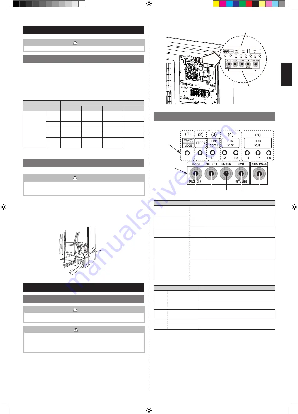
6.2. Description of display and buttons
• The printed characters for the LED display are shown below.
S134
S133
S132
S131
S130
LED display part
Button part
Display lamp
Function or operation method
(1) POWER / MODE
Green
Lights on while power on. Local setting in out-
door unit or error code is displayed with blink.
(2) ERROR
Red
Blinks during abnormal air conditioner
operation.
(3) PUMP DOWN
(L1)
Orange
Lights on during pump down operation.
(4) LOW NOISE
(L2, L3)
Orange
Lights on during Low noise mode when local
setting is activated. (Lighting pattern of L2 and
L3 indicates low noise level)
*Refer to the page 14.
(5) PEAK CUT
(L4, L5, L6)
Orange
Lights on during Peak cut mode when local
setting is activated. (Lighting pattern of L4, L5
and L6 indicates peak cut level)
*Refer to the page 15.
Button
Function or operation method
S134
MODE
To switch between “Local setting” and “Error code
display”.
S133
SELECT
To switch between the individual “Local settings”
and the “Error code displays”.
S132
ENTER
To
fi
x the individual “Local settings” and the “Error
code displays”.
S131
EXIT
To return to “Operation status displays.”
S130
PUMP DOWN
To start the pump down operation.
9379069953_IM.indb 13
9379069953_IM.indb 13
5/24/2019 9:59:20 AM
5/24/2019 9:59:20 AM