Micro-CS Installation Guide
A-1
APPENDIX A
PORT PIN/SIGNAL ALLOCATIONS
A.1
GENERAL
This appendix identifies the signals and the associated pins used by the
following Micro-CS ports:
•
Console
•
Serial
A.2
CONSOLE PORT
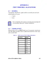
When the Micro-CS is in SETUP mode, port 1 becomes the console port.
The cable shipped with the Annex Communication Software can be used
as the console cable.
NOTE
Port 1 of the Micro-CS serves as a console port only during Set
Up. At all other times, port 1 acts as a serial port.
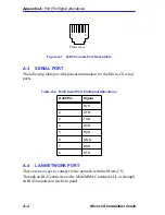
Table 1-1
RJ45 Console Port Pin/Signal Allocations
RJ45 Pin
Signal
1
RTS
2
DTR
3
TXD
4
CD
5
RXD
6
GND
7
DSR
8
CTS
Summary of Contents for MICRO-CS
Page 2: ......
Page 8: ...vi Micro CS Installation Guide...
Page 12: ...Contents iv Micro CS Installation Guide...
Page 22: ...Chapter 1 Introduction 1 10 Micro CS Installation Guide...
Page 32: ...Chapter 2 Micro CS Installation 2 10 Micro CS Installation Guide...
Page 72: ...Chapter 4 Troubleshooting Procedures 4 14 Micro CS Installation Guide...
Page 82: ...Appendix C Flash Upgrade Instructions C 4 Micro CS Installation Guide...

