BWT Pool'N Box Junior, Installation And Operating Instructions Manual
The "BWT Pool'N Box Junior" is a versatile and compact pool maintenance system for both above-ground and in-ground pools. To ensure a hassle-free installation and optimal performance, we provide an easy-to-follow "Installation And Operating Instructions Manual". Download this comprehensive manual for free from our website and get started with enjoying your clean and balanced pool.
Share
Download


Reviews:
No comments
Related manuals for Pool'N Box Junior

Accu-Tab 3000 Series
Brand: Axiall Pages: 6
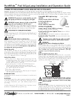
J&J Electronics PureWhite LPL-P2-WHT-12
Brand: Halco Pages: 2

Quick Set Ring Pool
Brand: SUMMER WAVES Pages: 28

ATLAS
Brand: Polaris Pages: 2

IN.K1000
Brand: HANSCRAFT Pages: 28

NC71AU
Brand: SmartPool Pages: 72

Aqua compact Series
Brand: Pahlen Pages: 7

EcoVISE
Brand: Pahlen Pages: 24

PG
Brand: Zodiac Pool Systems Pages: 11

Poolspot 7504613
Brand: ubbink Pages: 32

400W
Brand: Waterman Pages: 56

EVENGLOW
Brand: PAL Pages: 6

PTE
Brand: Modine Manufacturing Pages: 12

35IO
Brand: Intex Pages: 7

Auto Cleaner
Brand: Intex Pages: 11

Krystal Clear 638G
Brand: Intex Pages: 12

Krystal Clear 602G
Brand: Intex Pages: 11

L ZS6220
Brand: Intex Pages: 24


