Burkert 8746 Operating Instructions Manual Download Page 1

Operating Instructions

Bedienungsanleitung 
Manuel d‘utilisation
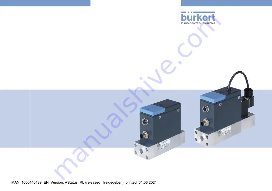
Type  8746

Profibus
Analogue

Mass Flow Meter (MFM) / Mass Flow Controller (MFC)
Massendurchflussmesser (MFM) / Massendurchflussregler (MFC)
Débitmètre massique (MFM) / Régulateur de débit massique (MFC)

Summary of Contents for 8746

Page 1: ...edienungsanleitung Manuel d utilisation Type 8746 Profibus Analogue Mass Flow Meter MFM Mass Flow Controller MFC Massendurchflussmesser MFM Massendurchflussregler MFC D bitm tre massique MFM R gulateu...

Page 2: ...ve the right to make technical changes without notice Technische nderungen vorbehalten Sous r serve de modifications techniques B rkert SAS 2020 2021 Operating Instructions 2103 01_EU ML_00573732 Orig...

Page 3: ...16 5 7 Control valve of an MFC 16 6 Technical data 17 6 1 Conformity 17 6 2 Standards 17 6 3 Operating conditions 17 6 3 1 Mass Flow Meter 17 6 3 2 Mass Flow Controller with proportional valve 18 6 3...

Page 4: ...nt shut off MFC 40 10 2 2 Flush mode MFC Profibus 41 10 3 Tools for doing settings 41 10 4 Connect the product to the B rkert Communi cator software 41 10 5 User defined adjustment 42 10 6 Operating m...

Page 5: ...adopts none of the values from the defective product 53 12 3 5 Replacement product does not adopt all of the values from the defective product 53 12 3 6 No mass flow rate MFM 53 12 3 7 No mass flow ra...

Page 6: ...s Flow Controller MFC Type 8746 Profibus Mass Flow Controller MFC Type 8746 Analogue 1 2 About NAMUR and the NAMUR Recommendation NE 107 Standards committee for measurement and control technology NAMU...

Page 7: ...mass flow rate of clean and dry gases Observe the data in the contract documents in the Operating Instructions on the Type label and on the calibration plate additional data operating conditions serv...

Page 8: ...operating company is responsible for the respect of the local safety regulations including for the personnel safety Risk of injury that is due to pressure in the installation or in the product Before...

Page 9: ...rt com In the event of any ambiguity please contact your local sales office Do not make any modifications to the product and do not subject the product to mechanical stress Protect the installation an...

Page 10: ...dress B rkert SAS Rue du Giessen F 67220 TRIEMBACH AU VAL The addresses of our international sales offices are available on the internet at country burkert com 4 2 Warranty The warranty is conditional...

Page 11: ...onnections according to DIN ISO 228 1 NPT internal threaded connections according to ASME ANSI B 1 20 1 flange connection 4 M4 screw for functional earth connection 5 Base block 6 Flow direction 7 Pro...

Page 12: ...nternal threaded connections according to ASME ANSI B 1 20 1 flange connection 4 M4 screw for functional earth connection 5 Base block 6 Flow direction 7 Proportional valve The proportional valve can...

Page 13: ...o ASME ANSI B 1 20 1 flange connection 4 M4 screw for functional earth connection 5 Base block 6 Flow direction 7 Motor valve 8 Status LED for the motor valve 9 Product status indicator The indicator...

Page 14: ...d MFC Due to a malfunction of the product or its periphery the measured values are not valid and the product cannot regulate any more Orange 4 Check function The product is being worked on MFM The out...

Page 15: ...cates the position of the motor valve The ambient conditions or the process conditions for the motor valve are outside the specified ranges green LED lit Motor valve is closed red LED flashing The col...

Page 16: ...e the data can be transferred from a defective product to a new product 5 6 b S interface The b S interface is used for short term servicing of the product with the B rkert Communicator software To co...

Page 17: ...ape Important product specific data is indicated on the Type label and the calibration plate Only use the product for the specified operating fluid Do not exceed the specified calibration pressure For...

Page 18: ...and tightened Operating pressure Max 10 bar Depends on the nominal diameter of the proportional valve 6 3 3 Mass Flow Controller with Type 3280 motor valve Tab 6 Operating conditions of an MFC with Ty...

Page 19: ...must be plugged in and tightened Operating pressure Max 22 bar Depends on the nominal diameter of the motor valve 6 4 Markings WARNING Risk of injury caused by pressure fluid escape Important product...

Page 20: ...mbol Observe the Operating Instructions deli vered with the product 5 Ambient temperature 6 Sealing material 7 Burst pressure 8 Manufacturing code 9 Class of the control valve according to the DVGW De...

Page 21: ...he related product 6 7 Fluid data 6 7 1 Mass Flow Meter Tab 12 Fluid data MFM Calibration fluid Operating gas or air Mass flow rate range reference to N2 IN min 20 2500 IN min Exact range depends on t...

Page 22: ...s then the measurement accuracy may be different because the composition of natural gas varies depending on the season and origin 6 7 3 Mass Flow Controller with motor valve Tab 14 Fluid data MFC with...

Page 23: ...ia of the fluid Criteria Quality class Value Maximum particle size 2 1 m Maximum particle density 2 1 mg m Maximum dew point under pressure 4 3 C Maximum oil concentration 1 0 01 mg m 6 7 5 Pressure l...

Page 24: ...ge C MFM with a base block for the 500 1500 lN min flow rate range Fig 8 Pressure loss diagram for air MFM with a 250 m mesh filter flow rate ranges 0 100 lN min 100 500 lN min 500 1500 lN min Q lN mi...

Page 25: ...ditions according to DIN 1343 PN 1013 25 mbar TN 273 15 K air density of air at the standard conditions according to DIN 1343 PN 1013 25 mbar TN 273 15 K Fig 10 Formula to calculate the pressure loss...

Page 26: ...current 20 mA Resolution 10 mV Relay output Normally closed contact break contact free of potential Tab 17 Electrical data of an MFC Operating voltage 24 V DC 10 15 V DC 10 on request residual ripple...

Page 27: ...Fluid installation 7 1 Safety instructions DANGER Risk of injury that is due to pressure in the installation or in the product Before working on the installation or product cut the pres sure Vent and...

Page 28: ...h G internal threaded fluid connections WARNING Risk of injury that is due to leakage At a low mass flow rate and a high pressure make sure that the installation is tight The tightness prevents incorr...

Page 29: ...ert If you use pipe fittings from another manufacturer obey the instructions from this manufacturer No inlet section is required The connection to the pipe is explained for one side of the product The...

Page 30: ...tion Tighten to a torque of 25 28 N m that is 18 44 20 65 lbf ft See Fig 14 C B Fig 14 Screw on the compression fitting body Insert the pipe in the compression fitting body Tighten the nut A by hand S...

Page 31: ...e pipes and from the fluid carrying components of the installation Cut the pipe squarely 1 and deburr 2 See Fig 17 1 2 Fig 17 Pipe cut and deburred NOTICE Malfunction that is due to contamination If a...

Page 32: ...connections clamp connections Install the product depending on the fitted fluid connections 8 Electrical installation 8 1 Safety instructions DANGER Risk of injury from electric shocks Before working...

Page 33: ...variant ATEX supplement for Type 8746 download from country burkert com 8 2 2 Product variant Profibus Product specific help in the B rkert Communicator software For an ATEX product variant ATEX supp...

Page 34: ...that are given by the manufacturer of the mating female connector Screw the mating female connector to the 5 pin male connector to the torque that is given by the manufacturer of the mating female con...

Page 35: ...of the 5 pin M12 female connector of an MFM or an MFC Tab 23 Default assignment of the digital input of the 5 pin M12 female connector Product variant Analogue Default assignment MFM No assignment MFC...

Page 36: ...ber 1 Changes to gas number 3 8 3 2 Relay output The 5 pin M12 female connector has a relay output The switching of the relay can show the following events MFC The set point value cannot be reached MF...

Page 37: ...the cable and conductors that are given by the manufacturer of the mating female connector and by the manufacturer of the mating male connector Use cables with a cable shielding that is either a brai...

Page 38: ...nctional earth To do the functional earthing of the product obey the following instructions Use a green and yellow cable that is as short as possible And the cable cross section must be at least equal...

Page 39: ...fluid 2 Flush the pipes with operating fluid at the calibration pressure 3 Vent the pipes completely 4 Energise the product If product specific data is stored on the inserted memory card then the prod...

Page 40: ...accident protection and all applicable safety regulations relating to the operating fluid used WARNING Risk of injury that is due to improper operation Improper operation can lead to injuries and dama...

Page 41: ...0 B rkert Communicator software To connect the product to the B rkert Communicator software refer to chpt 10 4 For general information about the B rkert Communicator software refer to the Type 8920 Op...

Page 42: ...define an adjustment procedure with up to 32 calibration points The user defined adjustment procedure is described in the prod uct specific Help of the B rkert Communicator software To connect the pro...

Page 43: ...n value y is equal to 10 then the opening of the control valve is 10 The transmission means of the set point value w and the measured value of the flow rate depend on the product Refer to chpt 10 7 1...

Page 44: ...losed loop control parameters must be optimised The function Autotune adapts the product to the new operating conditions When the Autotune is running Do not interrupt the power supply to the MFC Keep...

Page 45: ...ogue input Manual set point value to manually give in a set point value for testing purposes or to make sure that the set point value is not overwritten by other fieldbus participants Stored set point...

Page 46: ...pres sure Vent and drain the pipes Risk of injury from electric shocks Before working on the installation or product switch off the power supply Make sure that nobody can switch the power supply on Ob...

Page 47: ...ing maintenance operations At regular intervals inspect the stainless steel mesh filter for contamination Refer to chpt 11 1 1 If the stainless steel mesh filter is contaminated then clean the mesh fi...

Page 48: ...ke sure that the mesh filter and the O ring are seated flat and not tilted Insert the flange plate 2 and the screws 1 Tighten the screws to a torque of 2 8 N m that is 2 06 lbf ft 11 2 Cleaning and re...

Page 49: ...oubleshooting 12 1 Problems shown by the product status indicator The product status indicator changes its colour based on the NAMUR recommendation NE 107 to show diagnostics events If several diagnos...

Page 50: ...hen send the product back to B rkert 2 Incorrect Autotune or Autotune aborted Make sure that the fluid flows through the product Do the Autotune again 3 The sensor the internal memory or the product i...

Page 51: ...s indicator is still yellow then send the product back to B rkert 12 1 8 Product status indicator is yellow MFC Identify the cause 1 One of the following values is out of specification The sensor or t...

Page 52: ...the authorized range 12 3 Miscellaneous problems 12 3 1 Product status indicator is off If the product status indicator is off then the product is not ener gised To solve this issue do the following...

Page 53: ...onfigure the new values of the replacement product To connect the product to the B rkert Communicator software refer to chpt 10 4 12 3 6 No mass flow rate MFM The pipes are too large or not yet fully...

Page 54: ...trol valve Reduce the operating pressure To eliminate the defect return the product to the manufacturer 12 3 11 Set point value at 0 control valve is closed no mass flow but a non zero mass flow rate...

Page 55: ...tem Article number USB b S interface set without power supply 772551 Straight 5 pin M12 female connector 772416 Straight 5 pin M12 male connector B coding 918198 Item Article number Straight 5 pin M12...

Page 56: ...untry burkert com 14 Decommissioning 14 1 Safety instructions DANGER Risk of injury that is due to pressure in the installation or in the product Before working on the installation or product cut the...

Page 57: ...the product is not protected in transport then the product can be damaged Removecables connectors product externalfiltersandinstallation equipment Protect the electrical interfaces with protective pl...

Page 58: ...mental damage that is due to parts contaminated by fluids Dispose of the product and its packaging in an environmen tally friendly manner Comply with applicable environmental and disposal regulations...

Page 59: ......

Page 60: ...www burkert com...

Reviews: