


47
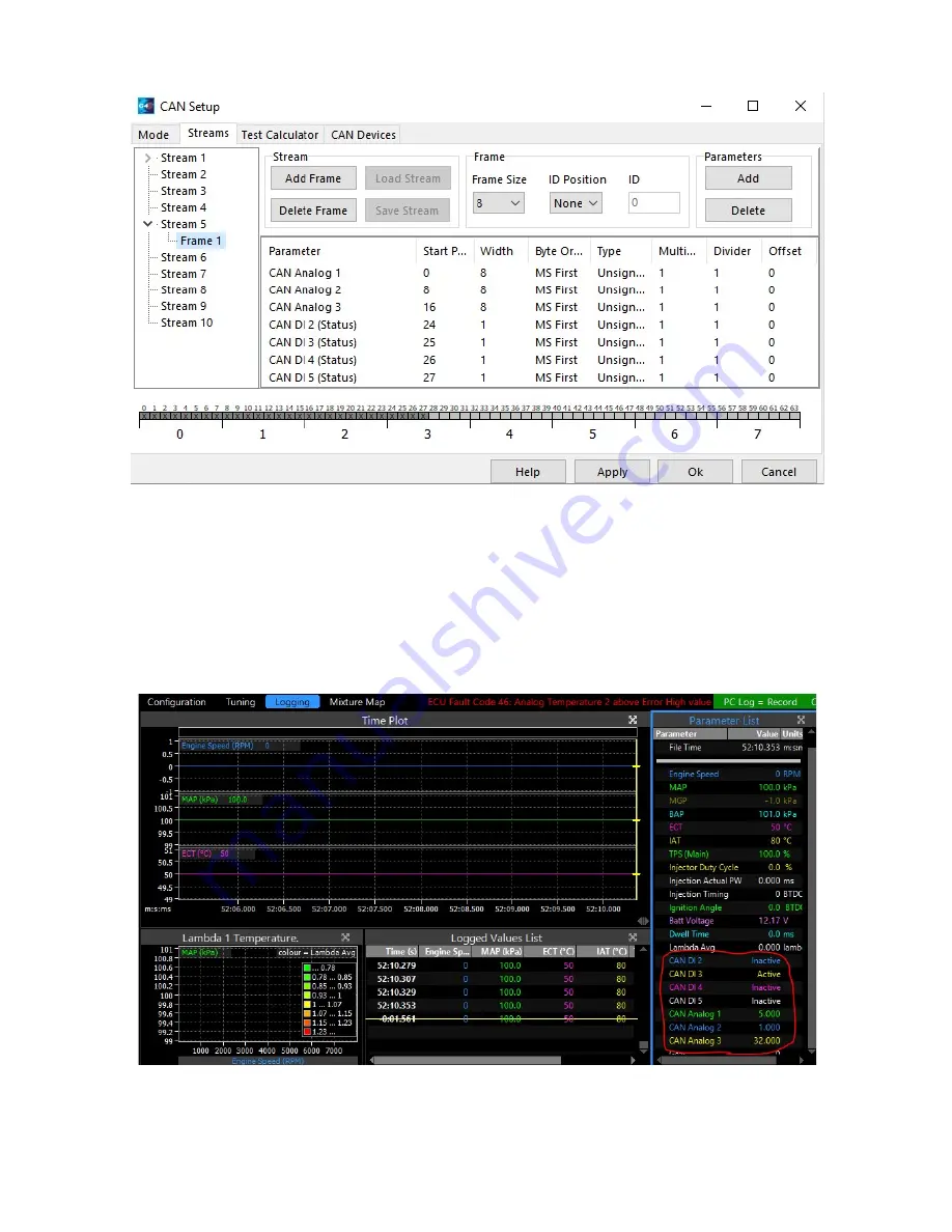
The Stream will then need to be configured. In this example we used Stream 5. Frame 1 will need to look
like this:
CAN Analog 1: 8 bit width Boost Control ( Value of 1-10 Boost PWM step dependant )
CAN Analog 2: 8 bit width
Slip Control ( Value of 1-10 Slip PWM step dependant )
CAN Analog 3: 8 bit width
AWD Bias ( Value 0-100 )
CAN DI 2 : 1 bit width
Antilag ( Value 0-1 )
CAN DI 3 : 1 bit width
Launch Control ( Value 0-1 )
CAN DI 4 : 1 bit width
Nitrous ( Value 0-1 )
CAN DI 5 : 1 bit width
Flat Shift ( Value 0-1 )
Note the potential values that may be sent with each Parameter. These parameters may be tested by
adding the relevant CAN parameters to the log viewer and testing the outputs:
Once the parameter communication has been verified, it is up to the user / tuner to take the
available data received and create a strategy in the PC Link software to perform the desired
function.
Summary of Contents for 4.3 TFT
Page 9: ...9 Example Boost Setup ...
Page 12: ...12 ...
Page 13: ...13 EMS 4 CAN Bus wiring ...
Page 30: ...30 ...
Page 32: ...32 ...
Page 38: ...38 ...
Page 48: ...48 MoTeC M1 Integration MoTeC M130 Connector Pin out MoTeC M142 and M150 Pin out ...
Page 49: ...49 MoTeC M170 Pin out A MoTeC M182 M190 Pin out ...


