background image


Electrical connection 


EcoGuide compact web guide control 


53/70 


7.5  Cable connections 

7.5.1  Cable connections for the EcoGuide size 1-3 

On the back panel of the 

ekr CON 100

 controller integrated in the 

EcoGuide

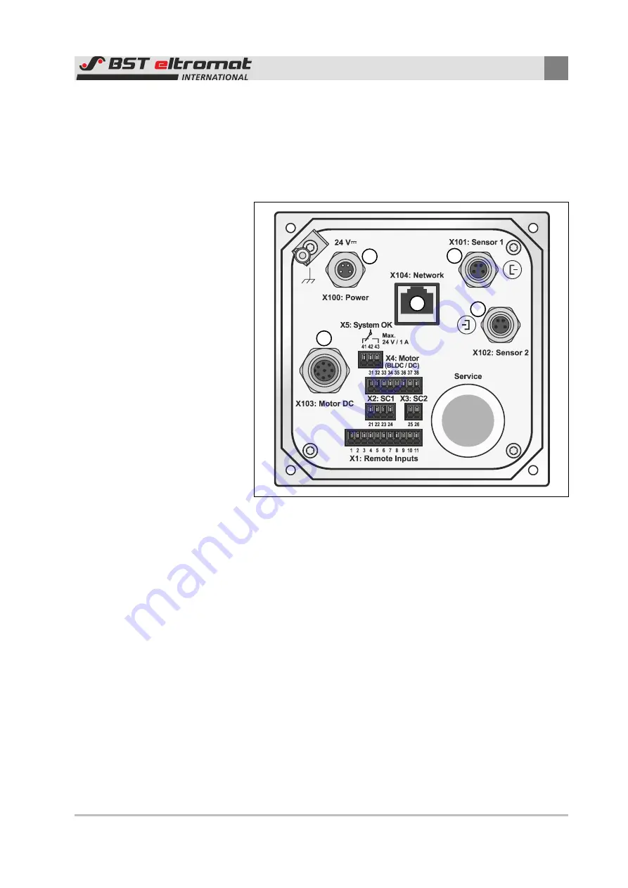
 the following sockets can be accessed: 


Fig. 29: Connections of the controller 


  Sensor 1 (edge sensor) 

  Sensor 2 (edge sensor) 

  Network (Ethernet) 

  Motor actuator 

  Power supply 


Summary of Contents for EcoGuide

Page 1: ...Compact web guide control Installation and operating instructions EcoGuide MD 464 EN 04 Translation of the original instructions...

Page 2: ...o bst international com Internet www bst international com This document is protected by copyright The translation as well as reproduction and distribution in any form is forbidden without the approva...

Page 3: ...tion of personnel 15 2 5 Obligations of the operating company and personnel 17 2 5 1 Obligations of the operating company 17 2 5 2 Obligations of the personnel 17 2 6 Conduct in the event of danger an...

Page 4: ...r and sensor holder 44 6 9 3 Preparing the sensor holder 45 6 9 4 Mounting the Sensor 46 7 Electrical connection 48 7 1 Safety instructions 48 7 2 Cable routing 49 7 3 Connecting the cables 50 7 4 Ens...

Page 5: ...ol 5 70 10 3 3 Cleaning the sensors 63 10 3 4 Cleaning the control panel 63 11 Troubleshooting 64 12 Accessories and spare parts 65 12 1 Order address 65 13 Customer Service 66 14 Shutting down and di...

Page 6: ...rts to form a complete machine and without influencing the safety and health of other persons These installation and operating instructions must be read and applied by every person who is involved in...

Page 7: ...ompany of the system 1 4 Meanings of the safety instructions and symbols 1 4 1 Safety instructions DANGER Danger that will be fatal or lead to severe injuries Here you can read how dangers can be avoi...

Page 8: ...4 Operating states of LEDs Some of the keys on the control panel have LEDs Light Emitting Diodes built into them The different LED operating states are represented as follows LED off LED illuminated a...

Page 9: ...6 42 EC Machinery Directive Commissioning of the compact web guide control is forbidden until the user operating company has de termined that the machine in which the system is installed con forms to...

Page 10: ...eb guiding system i e installation commissioning operation maintenance etc Intended use also includes adhering to the instructions given in this instruction manual Use for any other purposes other tha...

Page 11: ...ess BST eltromat products via networks Writing deleting and editing of system data files on BST el tromat products is not permitted Excepted from this is service work carried out at the instruction of...

Page 12: ...ger from electric shock Life threatening injuries caused by incomplete switching off or re sidual current With defective insulators or live parts switch off the power supply immediately and have the r...

Page 13: ...mergency stop equipment There is a risk of severe injuries if emergency stop equipment emergency stop button is not fitted on the entire system Only emergency stop equipment can stop the system immedi...

Page 14: ...here 2 3 2 Safety instructions for installation Before starting installation work Read the safety instructions in the production machine operat ing manual in which the compact web guide control is to...

Page 15: ...ct web guide control into the production machine never remove any safety equipment Never decommission safety equipment If the removal of safety equipment is necessary for installing the compact web gu...

Page 16: ...nowledge and experience as well as knowledge in the relevant regulations Carrying out the tasks assigned to them Recognizing possible hazards Undertaking appropriate measures for avoiding the hazards...

Page 17: ...es and checking their correct condition Information and training of the personnel for safe conduct intended use safety equipment prevention of hazards and conduct in the event of emergencies Provision...

Page 18: ...and accidents Preventative Measures Emergency and rescue equipment must be ready for use in every company These include for example emergency stop buttons fire extinguisher first aid kit and equipmen...

Page 19: ...to their products that originate from non intended use see Non intended use page 10 Liability for defects does also not apply if the fault originates from one or more of the following causes Catastrop...

Page 20: ...dy or health and results from a willful or grossly negligent breach of duty on the part of BST eltromat International GmbH or its legal representa tives or vicarious agents The form of damage can usua...

Page 21: ...ulleys Housing Controller with keyboard Actuator One or two edge sensors optical sensors or ultrasonic sensors Fig 1 EcoGuide Controller with keyboard Top frame Deflection pulley Edge sensor Sensor ad...

Page 22: ...information to the integrated controller The controller compares the ACTUAL recorded position against the default SETPOINT position The controller will send a relevant correction signal to the actuat...

Page 23: ...tionship applies between the selector switches and the scanning type for the sensors Symbol Designation Position Sensor 1 Left web edge Sensor 2 Right web edge The following is valid for the sensor in...

Page 24: ...4 1 Standard sizes 4 1 1 Size 1 3 Fig 4 Dimensional drawing EcoGuide Size Width Y mm Roll length L mm Correction length C mm Rolls D mm Controllable error mm Max web tension N 1 280 150 180 200 60 15...

Page 25: ...90 4 3 Protection class Protection class IP 40 4 4 Voltage supply Connector X100 Voltage 24 V 10 including ripple Current Max 2 5 A Connection 4 pin micro style connector M8 Max length of connecting c...

Page 26: ...3SEOP156765 Ultrasonic edge sensor US 2010 Fork width 40 mm Measuring range 12 mm 6 mm Supply voltage 12 to 30 V including ripple Current consumption 40 mA 24 V Ultra sonic frequency 164 kHz Output si...

Page 27: ...When being used in countries that have defined deviations to IEC 61010 1 these must also be observed The 0 V connection of the power pack must be connected with the protective conductor system see re...

Page 28: ...n marked Avoid causing damage to the packaging Replace damaged packaging with appropriate new packaging in order to avoid subsequent damage to the compact web guide control BST eltromat International...

Page 29: ...r only at the intended fixing points and on ly when using suitable slings Do not fix the lifting gear on the handles Secure the bearing ropes so that they cannot slip Transport the system components o...

Page 30: ...kaging cartons Check the components supplied for damage e g dents scratches loose parts defective cables etc Defective or de formed components must be replaced immediately as trouble free function of...

Page 31: ...screwed tight Before starting with the installation work Read the safety instructions in the operating instructions of the machine in which the BST eltromat components are to be in stalled Observe th...

Page 32: ...move any transport locks present from the BST eltromat components 6 2 Selecting the installation location DANGER Danger of death when operated in potentially explosive areas The system must never be i...

Page 33: ...g defective components during maintenance work 6 4 Tools and auxiliary material For the installation of a EcoGuide compact web guide control in the standard version in the production machine you need...

Page 34: ...he opti mum wrapping angle is 90 2 Pivoting frame 3 Sensor The sensor should be positioned at the very end of the first third of the outfeed path 4 Last fixed roll after the outfeed roll The wrapping...

Page 35: ...x the maximum web width 6 5 1 Alignment of the compact web guide control Observe the precise alignment of the compact web guide control The support surface on which the compact web guide control is g...

Page 36: ...mpact web guide control Fig 7 Horizontal alignment 6 5 2 Deflection pulleys Fig 8 Position of the deflection pulleys Last fixed roll before the infeed roll First fixed roll after the outfeed roll ekr...

Page 37: ...n positions Fig 9 Permissible installation positions When delivered from the factory the compact web guide control is prepared for installation in installation position W1U1 The ekr CON 100 controller...

Page 38: ...om the securing hole template in chapter 6 7 2 NOTE Damage to the system from drilling dust and loose parts Drilling dust splitter and loose parts may damage the machine Before carrying out drilling o...

Page 39: ...andard sizes 1 3 of the compact web guide control see also the following table Fig 11 Securing hole template for EcoGuide sizes 1 3 Size Housing width Y mm Correction length C mm Borehole distance Y 3...

Page 40: ...of the controller please go through the steps as follows 1 Disconnect all cable connections from the controller see pos 1 in fig 13 2 Remove the cable tie see pos 2 in fig 13 from the assembly bracke...

Page 41: ...ixing screws see fig 15 Fig 15 Fix the controller pass through the cables NOTE Damage caused by top frame bumping against the controller If the controller is mounted too close to the top frame it may...

Page 42: ...roller Top Frame 5 Pass through the connecting cables to the controller see fig 15 6 Connect all connecting cables to the controller again see fig 17 Fig 17 Connecting the cables 7 Fix the connecting...

Page 43: ...ble tie 6 9 Changing the mounting position of a sensor mounting an additional sensor Fig 19 EcoGuide with a sensor mounted on the left side If it is necessary to change the mounting position of a sens...

Page 44: ...20 2 Move the mounting rail to the outmost position determined by the threaded holes marked with position 3 in fig 20 Fig 20 Moving the mounting rail example for the right side 6 9 2 Removing sensor a...

Page 45: ...ing the sensor holder Before you can mount the sensor in a new mounting position the sensor holder needs to be prepared Please go through the steps as follows 1 Remove the t slide see pos 1 in fig 22...

Page 46: ...eps as follows 1 Slide the sensor holder onto the mounting rail see fig 24 2 Slide the sensor holder to the desired position on the mounting rail and fix it by means of the locking screw Fig 24 Slidin...

Page 47: ...Installation 6 EcoGuide compact web guide control 47 70 Fig 25 Mounting the sensor 2 1...

Page 48: ...PE connection Life threatening electric shock and destruction of system compo nents caused by short circuits Have electrical connections carried out by qualified electricians only Carry out PE connect...

Page 49: ...bending radius Maintain a minimum distance of at least 25 mm between the cables and moving parts of the machine Route the cables so that they do not rub or become crushed cut or caught Tighten up the...

Page 50: ...the metal sleeves fitted on the core end sleeve must be at least 8 mm For crimping we recommend the crimping pliers VarioC rimp 4 Zange 206 204 from Wago Cables from 0 75 mm2 to max 1 5 mm2 Connect th...

Page 51: ...Install conducting connections that permit equipotential bond ing of low and high frequencies between the individual ma chine parts or cable ducts Install ESD discharge devices before and after the in...

Page 52: ...r the connection of a cable for the equipotential bonding wire cross section 1 5 2 5 mm2 please use the push on con nector on the flat connector on the back of the controller Establish the equipotenti...

Page 53: ...Cable connections for the EcoGuide size 1 3 On the back panel of the ekr CON 100 controller integrated in the EcoGuide the following sockets can be accessed Fig 29 Connections of the controller Senso...

Page 54: ...e compact web guide con trol Before connecting the voltage supply make sure that the pow er pack used fulfills the requirements according to chapter 4 6 7 6 2 Connecting the voltage supply The voltage...

Page 55: ...witches block opposite function keys of the con trol panel If a remote control signal is set at the relevant terminals then you can no longer switch over the assigned functions from the control panel...

Page 56: ...njuries caused by incomplete switching off or re sidual current Electrically isolate the controller Secure the power supply against being switched back on Check that the unit is voltage free Earth the...

Page 57: ...ed in exceptional cases e g replacement of components If alterations of the setup are necessary they have to be done on the ekr CON 100 controller integrated in the EcoGuide Infor mation on the proced...

Page 58: ...web guide control is equipped with two edge sensors for web center line guiding With web edge guiding control on the left or right web edge the position of the respective edge sensor must be set 1 Sto...

Page 59: ...al position manu ally Ideally in its nominal position the material web runs cen trally over both deflection pulleys of the pivoting frame Fig 33 Thread in the material web 6 Carefully push the sensors...

Page 60: ...on 60 70 EcoGuide compact web guide control 9 2 Operating the ekr CON 100 controller The general operation of the ekr CON 100 controller is described in detail in the operating manual ekr CON 100 EDP...

Page 61: ...ainst it be ing switched back on DANGER Mortal danger from electric shock Life threatening injuries caused by incomplete switching off or re sidual current Electrically isolate the controller Secure t...

Page 62: ...eekly Prior to each material setup 10 3 3 Control panel Cleaning the housing Weekly 10 3 4 10 3 Maintenance and cleaning work 10 3 1 Cleaning the housing of the compact web guide control Cleaning the...

Page 63: ...t lenses of optical sensors or the transmission receiver capsules of ultrasonic sensors must be cleaned once a week A material set up must be run after the measuring lenses or transmission and receive...

Page 64: ...Only have the faults rectified by BST eltromat customer ser vices with the following measures or according to their instruc tions All safety instructions in the chapter Maintenance and cleaning must b...

Page 65: ...d spare parts 12 1 Order address Accessories and spare parts can be purchased under the following address BST eltromat International GmbH Heidsieker Heide 53 D 33739 Bielefeld Germany Tel 49 0 5206 99...

Page 66: ...ss In order to be able to reply to your request as soon as possible please provide us with the following data where available Product name Job number EDP number and software version Serial number and...

Page 67: ...is installed The necessary procedure must be prepared by the manufacturer of the machine To a great extent the system is made from electric electronic components and materials that depending on the c...

Page 68: ...51 ESD 14 ESD protection 14 F Firmware 6 Adding firmware 6 Functional principle 22 Further information 8 G Guarantee 19 Guarantee terms 19 H Housing width 39 I Iits intended purpose 9 Infeed path 35 I...

Page 69: ...nsor Changing the mounting position 43 Mounting 46 Sensors 25 Definition Sensor 1 and 2 23 Optical 25 Technical specifications 25 Ultrasonic 26 Set position 59 Settings for commisoning 57 Shutting dow...

Page 70: ...Declaration of incorporation 70 70 EcoGuide compact web guide control...

Reviews: