III - 60C
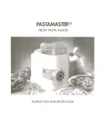
(10) Open the presser plate, then tighten two screws, as shown in Fig. 3.74C.
Note 9: Tighten those screws twice.
Presser plate
Adjustment jig
Screws
Main chassis
(11) Remove the presser jig assy (part of the presser base assy) and adjustment jig.
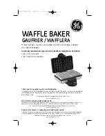
(12) Attach the presser plate cover to the presser plate, as shown in Fig. 3.74D.
Note 10: Check that two hooks and locating pins of the presser plate cover fit in
the
holes of the presser plate.
Presser plate cover
Presser plate
Hooks
Main chassis
Locating pins
Fig. 3.74C
Fig. 3.74D
Summary of Contents for SC-2000
Page 1: ...Stamp Creator PRO SERVICE MANUAL MODEL SC 2000 Version A ...
Page 2: ...Stamp Creator PRO SERVICE MANUAL MODEL SC 2000 ...
Page 13: ...I 7 Fig 1 6 ID Label 1438 Fig 1 7 ID Label 1850 Fig 1 8 ID Label 2770 ...
Page 118: ...II 4 Fig 2 2 Block Diagram of the Electronic Part ...
Page 132: ...III 14 Fig 3 15 Stamp Size Detection Open Cover Detection and Key Scanning Circuit ...
Page 138: ...III 20 Fig 3 21 Control Panel PCB Circuit ...
Page 144: ...APP 1 ...
Page 145: ...APP 2 ...
Page 146: ...APP 3 ...
Page 147: ...APP 4 D 100V AC System Power Supply Circuit ...
Page 148: ...APP 5 E 200V AC System Power Supply Circuit ...
Page 149: ...APP 6 ...
Page 150: ...Sep 98 5V5014BE0 Printed in Japan ...