3 - 22
Main parts
Main unit
33
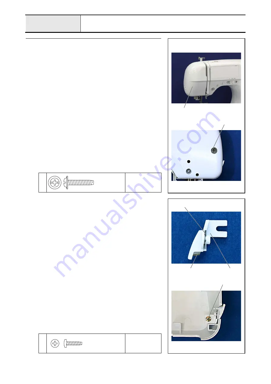
Face plate A assy. attachment
1. Attach the face plate A assy.
1
with the screw
1
.
1
Torque
0.78 — 1.18 N
·
m
1
1
Taptite, Cup P
M
4X20
33-1
Face plate A assy. assembly
1. Attach the NT lower thread cutter
2
to the cutter cover
1
, and then attach
the CS retaining ring
3
.
*Key point
• Insert the narrow edge of the NT lower thread cutter
2
into
the cutter cover
1
first.
• Align the tab of the CS retaining ring with the groove on the
shaft of the cutter cover
1
.
2. Attach the cutter cover assy. to face plate A
4
with the screw
1
.
1
Torque
0.39 — 0.78 N
·
m
3
2
1
1
Taptite, Bind B
M3X12
Summary of Contents for HS-3000
Page 1: ......
Page 2: ......
Page 3: ......
Page 9: ...vi ...
Page 16: ...2 1 2 Disassembly Main parts 2 2 Feed unit 2 22 Needle presser unit 2 30 ...
Page 17: ...2 2 Main parts Main parts location diagram Main unit ...
Page 37: ...2 22 Feed unit location diagram Main unit ...
Page 45: ...2 30 Needle presser unit location diagram Main unit ...
Page 55: ...3 2 Main parts Main parts location diagram Main unit ...
Page 77: ...3 24 Main unit Main parts 36 Accessory table attachment 1 Attach the accessory table 1 1 ...
Page 78: ...3 25 Assembly Feed unit Feed unit location diagram Main unit ...
Page 90: ...3 37 Assembly Needle presser unit Needle presser unit location diagram Main unit ...
Page 163: ...7 12 ...
Page 164: ......


