i
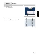
Accessory table removal ................................................................................................................... 2 - 3
Base cover removal ........................................................................................................................... 2 - 3
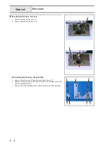
Needle plate B assy. removal ............................................................................................................ 2 - 4
Front cover assy. removal ................................................................................................................. 2 - 6
Thread guide assy. A removal .......................................................................................................... 2 - 7
Thread guide assy. B removal ........................................................................................................... 2 - 8
SSVR PCB assy. removal ................................................................................................................. 2 - 9
Buttons removal ................................................................................................................................ 2 - 9
LED lamp removal ............................................................................................................................ 2 - 9
Operation PCB assy. removal ......................................................................................................... 2 - 10
Selecting and manual buttons removal ........................................................................................... 2 - 10
Single light guide assy. removal ..................................................................................................... 2 - 10
Mode select PCB assy. removal ..................................................................................................... 2 - 10
SV keytop removal ......................................................................................................................... 2 - 11
Panel cover assy. removal .............................................................................................................. 2 - 12
Base plate rubber removal .............................................................................................................. 2 - 13
Upper cover thread guide removal .................................................................................................. 2 - 13
Main PCB assy. removal ................................................................................................................ 2 - 13
Power PCB assy. removal ............................................................................................................... 2 - 14
Inlet assy. removal .......................................................................................................................... 2 - 14
FC jack removal .............................................................................................................................. 2 - 15
Main motor assy. removal .............................................................................................................. 2 - 15
Spring removal ................................................................................................................................ 2 - 16
Feed unit assy. removal ................................................................................................................. 2 - 17
Upper shaft assy. removal ............................................................................................................... 2 - 17
Needle-presser unit removal ........................................................................................................... 2 - 18
Plate spring removal ....................................................................................................................... 2 - 18
Bobbin base assy. removal .............................................................................................................. 2 - 19
Bobbin winder assy. removal .......................................................................................................... 2 - 19
Spool pin removal ........................................................................................................................... 2 - 20
Bobbin presser removal .................................................................................................................. 2 - 20
Thread guide assy. removal ............................................................................................................ 2 - 20
Base plate rubber removal .............................................................................................................. 2 - 21
Summary of Contents for HS-3000
Page 1: ......
Page 2: ......
Page 3: ......
Page 9: ...vi ...
Page 16: ...2 1 2 Disassembly Main parts 2 2 Feed unit 2 22 Needle presser unit 2 30 ...
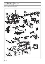
Page 17: ...2 2 Main parts Main parts location diagram Main unit ...
Page 37: ...2 22 Feed unit location diagram Main unit ...
Page 45: ...2 30 Needle presser unit location diagram Main unit ...
Page 55: ...3 2 Main parts Main parts location diagram Main unit ...
Page 77: ...3 24 Main unit Main parts 36 Accessory table attachment 1 Attach the accessory table 1 1 ...
Page 78: ...3 25 Assembly Feed unit Feed unit location diagram Main unit ...
Page 90: ...3 37 Assembly Needle presser unit Needle presser unit location diagram Main unit ...
Page 163: ...7 12 ...
Page 164: ......


