6 - 6
Repair Manual
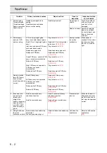
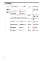
10 Threading not
possible
Thread pushed out at the hook
end
Threading
function
Check that when
threading is carried out
with Schappe Spun
Sewing Thread #60 /
#11 needle and
Schappe Spun Sewing
Thread #30 / #16
needle, that the
threading lever moves
smoothly and that
threading through the
needle hole is possible.
• Vertical slippage in needle
thread block
Adjust needle thread
Hook extends right of the needle
hole
• Wide gap between right side
of needle and hook guide
Replace threader hook assy.
• Needle curvature
Replace needle
• Needle slant (hole slant with
slanted attachment of
needle block)
Replace needle bar
• Threader hook assy.
slippage
Replace threader hook assy.
When the threader
lever returns, it
stops part way
through.
Threader shaft tangling
Replace needle holder assy.
Bad thread guide shape
Replace threader hook assy.
Needle thread shaft and top gap
too small
Replace needle holder assy.
Needle thread
lever operation
catches part way
through.
Bad needle stop position
• NP sensor damage
Replace main PCB assy.
• Grease or dirt adhering to
NP sensor
Remove grease and dirt
• Rotation shutter damage
Replace upper shaft assy.
• Bad needle thread block
rotational position
Adjust needle thread block
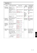
11 Either upper thread
tension or lower
thread tension
Upper thread tension is tight/
loose
Adjust upper thread tention
Upper thread
tension
Check that the thread
tension is good during
actual sewing.
Lower thread tension is too tight/
loose
Adjust lower thread tension
Lower thread
tension
Upper thread or lower thread
unsuitable
Replace upper thread or lower
thread
Problem
Primary factors and causes
Repair method
Items for
Inspection
Inspection method
and standards
Summary of Contents for HS-3000
Page 1: ......
Page 2: ......
Page 3: ......
Page 9: ...vi ...
Page 16: ...2 1 2 Disassembly Main parts 2 2 Feed unit 2 22 Needle presser unit 2 30 ...
Page 17: ...2 2 Main parts Main parts location diagram Main unit ...
Page 37: ...2 22 Feed unit location diagram Main unit ...
Page 45: ...2 30 Needle presser unit location diagram Main unit ...
Page 55: ...3 2 Main parts Main parts location diagram Main unit ...
Page 77: ...3 24 Main unit Main parts 36 Accessory table attachment 1 Attach the accessory table 1 1 ...
Page 78: ...3 25 Assembly Feed unit Feed unit location diagram Main unit ...
Page 90: ...3 37 Assembly Needle presser unit Needle presser unit location diagram Main unit ...
Page 163: ...7 12 ...
Page 164: ......

