


HL-5130/5140/5150D/5150DN Service Manual
4-47
3.20 Engine
PCB
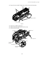
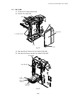
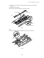
(1) Disconnect the connectors.
Fig. 4-82
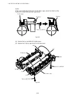
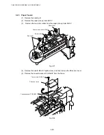
(2) Remove the two bind B M4x12 Taptite screws, and then remove the engine PCB ASSY.
Fig. 4-83
Taptite, bind B M4x12
Engine PCB ASSY
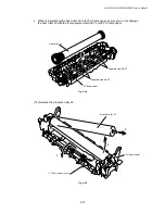
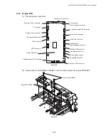
Engine PCB ASSY
Toner sensor
(light reception) connector
Thermistor relay PCB connector
Main motor connector
Main PCB connector
MP tray PCB connector
FR solenoid connector
PF solenoid connector
Fan motor 60 unit connector
LT connector
Polygon motor connector
Fan motor 60 connector
LVPS connector
Cassette sensor PCB connector
Toner sensor
(light emission) connector
HVPS connector
DX rear cover connector
DX solenoid connector
DX sensor PCB connector


