


V
- 1
1.
ENTRY INTO THE MAINTENANCE MODE
FAX3750/MFC7750: To make the equipment enter the maintenance mode, press the
Function
,
*
,
2
,
8
,
6
, and
4
keys in this order.
Within 2 seconds
FAX-8650P: To make the equipment enter the maintenance mode, press the
Menu
,
*
,
2
,
8
,
6
, and
4
keys in this order.
Within 2 seconds
The equipment beeps for approx. one second and displays "
" on the
LCD, indicating that it is placed in the initial stage of the maintenance mode, a mode in which the
equipment is ready to accept entry from the keys.
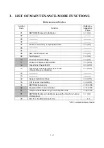
To select one of the maintenance-mode functions listed in Section 2, enter the corresponding 2-
digit function code with the numerical keys on the control panel. (The details of each
maintenance-mode function are described in Section 3.)
NOTES:
• Pressing the
9
key twice in the initial stage of the maintenance mode makes the
equipment exit from the maintenance mode, restoring it to the standby state.
• Pressing the
Stop
key after entering only one digit restores the equipment to the
initial stage of the maintenance mode.
• If an invalid function code is entered, the equipment resumes the initial stage of the
maintenance mode.
Summary of Contents for FAX-8650P
Page 1: ...FACSIMILE EQUIPMENT SERVICE MANUAL MODEL FAX3750 FAX 8650P MFC7750 ...
Page 5: ...CHAPTER I GENERAL DESCRIPTION ...
Page 12: ...CHAPTER II INSTALLATION ...
Page 13: ...CONTENTS 1 INSTALLING THE UPDATE DATA TO THE FACSIMILE EQUIPMENT II 1 ...
Page 16: ...CHAPTER III THEORY OF OPERATION ...
Page 18: ...III 1 1 OVERVIEW Not provided on the FAX 8650P ...
Page 28: ...III 11 Not provided on the FAX 8650P Location of Sensors and Actuators ...
Page 31: ...III 14 Main PCB Modem PCB ...
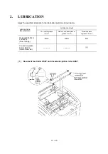
Page 36: ...CHAPTER IV DISASSEMBLY REASSEMBLY AND LUBRICATION ...
Page 42: ...IV 4 n n Disassembly Order Flow ...
Page 71: ...IV 33 1 Provided on the FAX 8650P 2 Not provided on the FAX 8650P ...
Page 72: ...IV 34 Setting up the main PCB after replacement ...
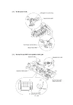
Page 84: ...IV 46 2 Control panel locks 3 Scanner frame ASSY and separation roller gear ...
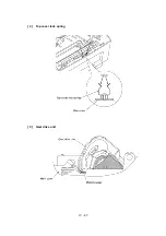
Page 85: ...IV 47 4 Top cover lock spring 5 Gear drive unit ...
Page 86: ...CHAPTER V MAINTENANCE MODE ...
Page 93: ...V 6 Scanning Compensation Data List ...
Page 141: ...V 54 FAX3750 FAX 8650P MFC7750 Key Button Entry Order ...
Page 146: ...CHAPTER VI ERROR INDICATION AND TROUBLESHOOTING ...
Page 171: ...Oct 98 SM5X5303 Printed in Japan ...
Page 172: ...FAX3750 FAX 8650P MFC7750 Appendix 1 EEPROM Customizing Codes ...
Page 194: ......
Page 195: ......
Page 196: ......


