


III
- 10
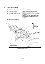
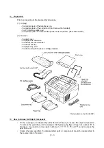
2.3
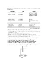
Sensors and Actuators
This equipment has ten sensors: seven photosensors, two thermisters and a mechanical switch as
described below.
Sensor name
Type
Located on
Document front sensor
Photosensor
Control panel PCB ASSY
(Document sensor PCB)
Document rear sensor
Photosensor
Control panel PCB ASSY
(Document sensor PCB)
Top cover sensor
Photosensor
Main PCB
Sheet feeder cover sensor
Photosensor
Main PCB
Registration sensor
Photosensor
Main PCB
Paper ejection sensor
Photosensor
High-voltage power supply
PCB
Toner sensor
Photosensor
Toner sensor PCB
Toner thermister
Thermister
Toner sensor PCB
Heater thermister
Thermister
Heat-fixing unit
Hook switch*
Mechanical switch
Hook switch PCB*
*Not provided on the FAX-8650P.
•
Document front sensor which detects the presence of documents.
•
Document rear sensor which detects the leading and trailing edges of pages to tell the control
circuitry when the leading edge of a new page has reached the starting position and when the
scan for that page is over.
•
Top cover sensor which detects whether the top cover is closed.
•
Sheet feeder cover sensor which detects whether the sheet feeder cover is closed.
•
Registration sensor which detects the leading and trailing edges of paper, which allows the
controller to determine the registration timing and check paper jam.
•
Paper ejection sensor which detects whether the recording paper goes out of the equipment.
•
Toner sensor which detects whether there is toner or a toner cartridge is loaded.
•
Toner thermister which detects the ambient temperature of the toner cartridge.
•
Heater thermister which detects the temperature of the heater roller of the fixing unit.
•
Hook switch* which detects whether the handset is placed on the handset mount.
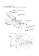
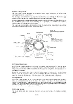
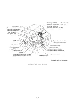
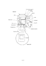
These photosensors are a photointerrupter consisting of a light-emitting diode and a light-sensitive
transistor. Each of them has an actuator separately arranged as shown on the next page.
Summary of Contents for FAX-8650P
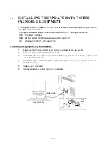
Page 1: ...FACSIMILE EQUIPMENT SERVICE MANUAL MODEL FAX3750 FAX 8650P MFC7750 ...
Page 5: ...CHAPTER I GENERAL DESCRIPTION ...
Page 12: ...CHAPTER II INSTALLATION ...
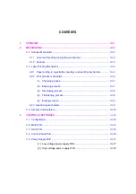
Page 13: ...CONTENTS 1 INSTALLING THE UPDATE DATA TO THE FACSIMILE EQUIPMENT II 1 ...
Page 16: ...CHAPTER III THEORY OF OPERATION ...
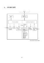
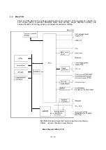
Page 18: ...III 1 1 OVERVIEW Not provided on the FAX 8650P ...
Page 28: ...III 11 Not provided on the FAX 8650P Location of Sensors and Actuators ...
Page 31: ...III 14 Main PCB Modem PCB ...
Page 36: ...CHAPTER IV DISASSEMBLY REASSEMBLY AND LUBRICATION ...
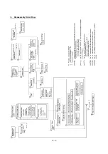
Page 42: ...IV 4 n n Disassembly Order Flow ...
Page 71: ...IV 33 1 Provided on the FAX 8650P 2 Not provided on the FAX 8650P ...
Page 72: ...IV 34 Setting up the main PCB after replacement ...
Page 84: ...IV 46 2 Control panel locks 3 Scanner frame ASSY and separation roller gear ...
Page 85: ...IV 47 4 Top cover lock spring 5 Gear drive unit ...
Page 86: ...CHAPTER V MAINTENANCE MODE ...
Page 93: ...V 6 Scanning Compensation Data List ...
Page 141: ...V 54 FAX3750 FAX 8650P MFC7750 Key Button Entry Order ...
Page 146: ...CHAPTER VI ERROR INDICATION AND TROUBLESHOOTING ...
Page 171: ...Oct 98 SM5X5303 Printed in Japan ...
Page 172: ...FAX3750 FAX 8650P MFC7750 Appendix 1 EEPROM Customizing Codes ...
Page 194: ......
Page 195: ......
Page 196: ......


