


V
- 20
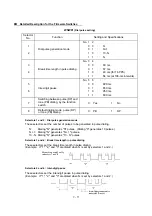
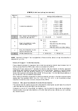
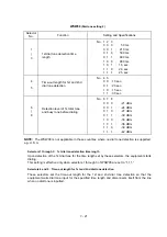
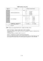
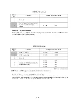
WSW07
(Dial tone setting 1)
Selector
No.
Function
Setting and Specifications
1
2
Frequency band range
No. 1 2
0 0
: Narrows by 10 Hz
0 1
: Initial value
1 X
: Widens by 10 Hz
3
Line current detection
0: No
1: Yes
4
|
6
2nd dial tone detection level
(Z = 600
Ω
)
No. 4 5 6
0 0 0 :
-21 dBm
0 0 1 :
-24 dBm
0 1 0 :
-27 dBm
0 1 1 :
-30 dBm
1 0 0 :
-33 dBm
1 0 1 :
-36 dBm
1 1 0 :
-39 dBm
1 1 1 :
-42 dBm
7
1st dial tone interrupt detecting
time
0: 30 ms
1: 50 ms
8
Not used.
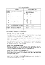
NOTE:
Selectors 1, 2, 4 through 7 are not applicable in those countries where no dial tone or line
current detection is supported, e.g., U.S.A.
l
l
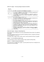
Selectors 1 and 2: Frequency band range
These selectors set the frequency band for the 1st dial tone and the busy tone (before dialing) to
be detected.
This setting is effective only when selectors 1 through 3 of WSW05 are set to “1,1,1.”
l
Selector 3:
Line current detection
This selector determines whether or not the equipment should detect a line current before starting
dialing.
l
Selectors 4 through 6: 2nd dial tone detection level
These selectors set the detection level of the 2nd dial tone.
l
Selector 7:
1st dial tone interrupt detecting time
This selector sets the allowable time length of an interrupt which should not be interpreted as an
interrupt in the 1st dial tone dialing.
Summary of Contents for FAX-8650P
Page 1: ...FACSIMILE EQUIPMENT SERVICE MANUAL MODEL FAX3750 FAX 8650P MFC7750 ...
Page 5: ...CHAPTER I GENERAL DESCRIPTION ...
Page 12: ...CHAPTER II INSTALLATION ...
Page 13: ...CONTENTS 1 INSTALLING THE UPDATE DATA TO THE FACSIMILE EQUIPMENT II 1 ...
Page 16: ...CHAPTER III THEORY OF OPERATION ...
Page 18: ...III 1 1 OVERVIEW Not provided on the FAX 8650P ...
Page 28: ...III 11 Not provided on the FAX 8650P Location of Sensors and Actuators ...
Page 31: ...III 14 Main PCB Modem PCB ...
Page 36: ...CHAPTER IV DISASSEMBLY REASSEMBLY AND LUBRICATION ...
Page 42: ...IV 4 n n Disassembly Order Flow ...
Page 71: ...IV 33 1 Provided on the FAX 8650P 2 Not provided on the FAX 8650P ...
Page 72: ...IV 34 Setting up the main PCB after replacement ...
Page 84: ...IV 46 2 Control panel locks 3 Scanner frame ASSY and separation roller gear ...
Page 85: ...IV 47 4 Top cover lock spring 5 Gear drive unit ...
Page 86: ...CHAPTER V MAINTENANCE MODE ...
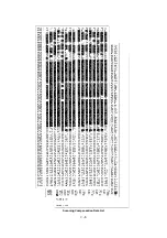
Page 93: ...V 6 Scanning Compensation Data List ...
Page 141: ...V 54 FAX3750 FAX 8650P MFC7750 Key Button Entry Order ...
Page 146: ...CHAPTER VI ERROR INDICATION AND TROUBLESHOOTING ...
Page 171: ...Oct 98 SM5X5303 Printed in Japan ...
Page 172: ...FAX3750 FAX 8650P MFC7750 Appendix 1 EEPROM Customizing Codes ...
Page 194: ......
Page 195: ......
Page 196: ......


