


III
- 5
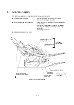
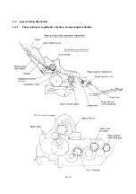
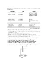
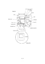
Paper pulling-in and registration mechanism
The paper pulling-in and registration mechanism consists of the pull-in roller gear (incorporated in
the multi-purpose sheet feeder), planetary gear system, paper feed solenoid, solenoid lever, clutch
release lever, and registration sensor. (For the details about the sensor, refer to Section 2.3.)
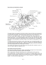
If the main motor rotates clockwise, the rotation is transmitted to the intermediate gear of the
planetary gear system. As the intermediate gear rotates, the pull-in roller drive gear also rotates
since the clutch gear is locked by the solenoid lever and the clutch release lever. Accordingly, the
pull-in roller in the multi-purpose sheet feeder rotates to pull in paper into the equipment, a sheet
at a time.
If the paper feed solenoid is retracted and the clutch release lever is operated according to the
cam profile of the pull-in roller gear so as to release the clutch gear, the clutch gear rotates and
the pull-in roller drive gear does not rotate. In this way, the clutch gear switches the transmission
of the motor rotation to the pull-in roller drive gear on and off.
The solenoid on/off timing and the clutch release lever timing allow this mechanism to pull in a
sheet and register it against the registration roller.
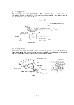
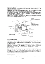
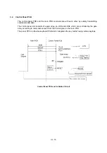
Paper feeding and ejecting mechanism
If the main motor rotates clockwise, the rotation is transmitted via the gear train to the drum drive
gear, heater roller drive gear, and paper ejection roller drive gear.
After the paper passes through the heat-fixing process, it will be ejected onto the paper tray.
If the leading edge of the paper pushes up the actuator of the paper ejection sensor, the
photosensor becomes opened, signaling the start of paper ejection. If the trailing edge has passed
through the sensor actuator, the sensor becomes closed, signaling the completion of paper
ejection. Then, the main motor stops rotation.
Summary of Contents for FAX-8650P
Page 1: ...FACSIMILE EQUIPMENT SERVICE MANUAL MODEL FAX3750 FAX 8650P MFC7750 ...
Page 5: ...CHAPTER I GENERAL DESCRIPTION ...
Page 12: ...CHAPTER II INSTALLATION ...
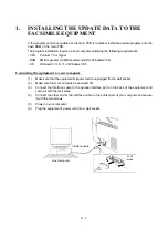
Page 13: ...CONTENTS 1 INSTALLING THE UPDATE DATA TO THE FACSIMILE EQUIPMENT II 1 ...
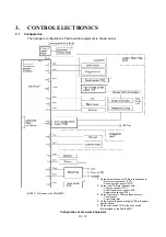
Page 16: ...CHAPTER III THEORY OF OPERATION ...
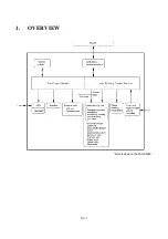
Page 18: ...III 1 1 OVERVIEW Not provided on the FAX 8650P ...
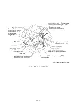
Page 28: ...III 11 Not provided on the FAX 8650P Location of Sensors and Actuators ...
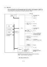
Page 31: ...III 14 Main PCB Modem PCB ...
Page 36: ...CHAPTER IV DISASSEMBLY REASSEMBLY AND LUBRICATION ...
Page 42: ...IV 4 n n Disassembly Order Flow ...
Page 71: ...IV 33 1 Provided on the FAX 8650P 2 Not provided on the FAX 8650P ...
Page 72: ...IV 34 Setting up the main PCB after replacement ...
Page 84: ...IV 46 2 Control panel locks 3 Scanner frame ASSY and separation roller gear ...
Page 85: ...IV 47 4 Top cover lock spring 5 Gear drive unit ...
Page 86: ...CHAPTER V MAINTENANCE MODE ...
Page 93: ...V 6 Scanning Compensation Data List ...
Page 141: ...V 54 FAX3750 FAX 8650P MFC7750 Key Button Entry Order ...
Page 146: ...CHAPTER VI ERROR INDICATION AND TROUBLESHOOTING ...
Page 171: ...Oct 98 SM5X5303 Printed in Japan ...
Page 172: ...FAX3750 FAX 8650P MFC7750 Appendix 1 EEPROM Customizing Codes ...
Page 194: ......
Page 195: ......
Page 196: ......


