


VI
- 7
n
n
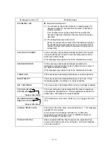
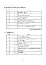
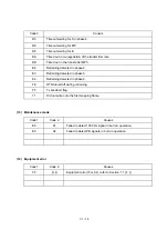
Definition of Error Codes on the Communications List
(1)
Calling
Code 1
Code 2
Causes
10
08
Wrong number called.
11
01
No dial tone detected before start of dialing.
11
02
Busy tone detected before dialing.
11
03
2nd dial tone not detected.
11
05
No loop current detected.*
11
06
Busy tone detected after dialing or called.
11
07
No response from the remote station in sending.
11
10
No tone detected after dialing.
17
07
No response from the calling station in receiving.
*Available in German versions only.
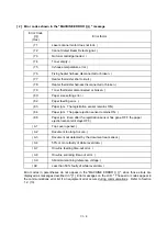
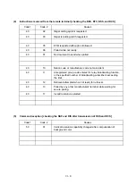
(2)
Command reception
Code 1
Code 2
Causes
20
01
Unable to detect a flag field.
20
02
Carrier was OFF for 200 ms or longer.
20
03
Abort detected ("1" in succession for 7 bits or more).
20
04
Overrun detected.
20
05
A frame for 3 seconds or more received.
20
06
CRC error in answerback.
20
07
Undefined command received.
20
08
Invalid command received.
20
09
Command ignored once for document setting or for dumping-out
at turn-around transmission.
20
0A
T5 time-out error
20
0B
CRP received.
20
0C
EOR and NULL received.
Summary of Contents for FAX-8650P
Page 1: ...FACSIMILE EQUIPMENT SERVICE MANUAL MODEL FAX3750 FAX 8650P MFC7750 ...
Page 5: ...CHAPTER I GENERAL DESCRIPTION ...
Page 12: ...CHAPTER II INSTALLATION ...
Page 13: ...CONTENTS 1 INSTALLING THE UPDATE DATA TO THE FACSIMILE EQUIPMENT II 1 ...
Page 16: ...CHAPTER III THEORY OF OPERATION ...
Page 18: ...III 1 1 OVERVIEW Not provided on the FAX 8650P ...
Page 28: ...III 11 Not provided on the FAX 8650P Location of Sensors and Actuators ...
Page 31: ...III 14 Main PCB Modem PCB ...
Page 36: ...CHAPTER IV DISASSEMBLY REASSEMBLY AND LUBRICATION ...
Page 42: ...IV 4 n n Disassembly Order Flow ...
Page 71: ...IV 33 1 Provided on the FAX 8650P 2 Not provided on the FAX 8650P ...
Page 72: ...IV 34 Setting up the main PCB after replacement ...
Page 84: ...IV 46 2 Control panel locks 3 Scanner frame ASSY and separation roller gear ...
Page 85: ...IV 47 4 Top cover lock spring 5 Gear drive unit ...
Page 86: ...CHAPTER V MAINTENANCE MODE ...
Page 93: ...V 6 Scanning Compensation Data List ...
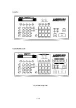
Page 141: ...V 54 FAX3750 FAX 8650P MFC7750 Key Button Entry Order ...
Page 146: ...CHAPTER VI ERROR INDICATION AND TROUBLESHOOTING ...
Page 171: ...Oct 98 SM5X5303 Printed in Japan ...
Page 172: ...FAX3750 FAX 8650P MFC7750 Appendix 1 EEPROM Customizing Codes ...
Page 194: ......
Page 195: ......
Page 196: ......


