


V
- 53
3.6
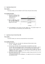
Operational Check of LCD
n
n
Function
This function allows you to check whether the LCD on the control panel works normally.
n
n
Operating Procedure
(1) Press the
1
and
2
keys in this
order in the initial stage of the
maintenance mode.
The LCD shows
(2) Press the
Start
key. Each
time you press the
Start
key,
the LCD cycles through the
displays shown at right.
(3) Press the
Stop
key in any process of the above display cycle. The equipment beeps for one
second and returns to the initial stage of the maintenance mode.
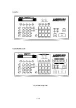
3.7
Operational Check of Control Panel PCB
n
n
Function
This function allows you to check the control panel PCB for normal operation.
n
n
Operating Procedure
(1) Press the
1
and
3
keys in this order in the initial stage of the maintenance mode.
The "00 " will appear on the LCD.
(2) Press the keys and buttons in the order designated in the illustration shown below.
The LCD shows the corresponding number in decimal notation each time a key or button is
pressed. Check that the displayed number is correct by referring to the illustration below.
If a key or button is pressed out of order, the equipment beeps and displays the "INVALID
OPERATE" on the LCD. To return to the status ready to accept key & button entry for
operational check, press the
Stop
key.
(3) After the last number key or button is pressed, the equipment beeps and returns to the initial
stage of the maintenance mode.
To terminate this operation, press the
Stop
key. The equipment returns to the initial stage of
the maintenance mode.
Summary of Contents for FAX-8650P
Page 1: ...FACSIMILE EQUIPMENT SERVICE MANUAL MODEL FAX3750 FAX 8650P MFC7750 ...
Page 5: ...CHAPTER I GENERAL DESCRIPTION ...
Page 12: ...CHAPTER II INSTALLATION ...
Page 13: ...CONTENTS 1 INSTALLING THE UPDATE DATA TO THE FACSIMILE EQUIPMENT II 1 ...
Page 16: ...CHAPTER III THEORY OF OPERATION ...
Page 18: ...III 1 1 OVERVIEW Not provided on the FAX 8650P ...
Page 28: ...III 11 Not provided on the FAX 8650P Location of Sensors and Actuators ...
Page 31: ...III 14 Main PCB Modem PCB ...
Page 36: ...CHAPTER IV DISASSEMBLY REASSEMBLY AND LUBRICATION ...
Page 42: ...IV 4 n n Disassembly Order Flow ...
Page 71: ...IV 33 1 Provided on the FAX 8650P 2 Not provided on the FAX 8650P ...
Page 72: ...IV 34 Setting up the main PCB after replacement ...
Page 84: ...IV 46 2 Control panel locks 3 Scanner frame ASSY and separation roller gear ...
Page 85: ...IV 47 4 Top cover lock spring 5 Gear drive unit ...
Page 86: ...CHAPTER V MAINTENANCE MODE ...
Page 93: ...V 6 Scanning Compensation Data List ...
Page 141: ...V 54 FAX3750 FAX 8650P MFC7750 Key Button Entry Order ...
Page 146: ...CHAPTER VI ERROR INDICATION AND TROUBLESHOOTING ...
Page 171: ...Oct 98 SM5X5303 Printed in Japan ...
Page 172: ...FAX3750 FAX 8650P MFC7750 Appendix 1 EEPROM Customizing Codes ...
Page 194: ......
Page 195: ......
Page 196: ......


