


V
- 55
3.8
Sensor Operational Check
n
n
Function
This function allows you to check whether the eight sensors (document front sensor, document
rear sensor, sheet feeder cover sensor, cover sensor, registration sensor, paper ejection sensor,
toner sensor, and hook switch sensor*) operate correctly.
(*The FAX-8650P has no hook switch sensor.)
In the FAX3750/MFC7750, the LCD shows the "FRRETCCVRGHATNHK" when
- the document front sensor detects no paper (FR),
- the document rear sensor detects no paper (RE),
- the sheet feeder cover is closed (TC),
- the top cover is closed (CV),
- the registration sensor detects no paper (RG),
- the paper ejection sensor detects no paper (HA),
- the toner sensor detects toner (TN), and
- the hook switch sensor detects the on-hook state (HK).
In the FAX-8650P, the LCD shows the "FRRETCCVRGHATN" when
- the document front sensor detects no paper (FR),
- the document rear sensor detects no paper (RE),
- the sheet feeder cover is closed (TC),
- the top cover is closed (CV),
- the registration sensor detects no paper (RG),
- the paper ejection sensor detects no paper (HA), and
- the toner sensor detects toner (TN).
n
n
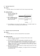
Operating Procedure
(1) Press the
3
and
2
keys in this order in the initial stage of the maintenance mode. The
equipment beeps 1100 Hz and 400 Hz tones cyclically through the following volumes for
testing the speaker.
NOTE:
To stop beeping, press the
Function
key (FAX3750/MFC7750) or
Menu
key (FAX-
8650P).
In the FAX3750/MFC7750, the LCD should show "FRRETCCVRGHATNHK" if the detecting
conditions of the eight sensors are as defined above.
In the FAX-8650P, the LCD should show "FRRETCCVRGHATN" if the detecting conditions of
the seven sensors are as defined above.
(2) Change the detecting conditions (e.g., insert paper through the document sensors or the
registration sensor, open the sheet feeder cover or the top cover, jam paper at the paper
outlet, remove the toner cartridge, and lift up the handset), and then check that the indication
on the LCD changes according to the sensor states.
(3) To stop this operation and return the equipment to the initial maintenance mode, press the
Stop
key.
Summary of Contents for FAX-8650P
Page 1: ...FACSIMILE EQUIPMENT SERVICE MANUAL MODEL FAX3750 FAX 8650P MFC7750 ...
Page 5: ...CHAPTER I GENERAL DESCRIPTION ...
Page 12: ...CHAPTER II INSTALLATION ...
Page 13: ...CONTENTS 1 INSTALLING THE UPDATE DATA TO THE FACSIMILE EQUIPMENT II 1 ...
Page 16: ...CHAPTER III THEORY OF OPERATION ...
Page 18: ...III 1 1 OVERVIEW Not provided on the FAX 8650P ...
Page 28: ...III 11 Not provided on the FAX 8650P Location of Sensors and Actuators ...
Page 31: ...III 14 Main PCB Modem PCB ...
Page 36: ...CHAPTER IV DISASSEMBLY REASSEMBLY AND LUBRICATION ...
Page 42: ...IV 4 n n Disassembly Order Flow ...
Page 71: ...IV 33 1 Provided on the FAX 8650P 2 Not provided on the FAX 8650P ...
Page 72: ...IV 34 Setting up the main PCB after replacement ...
Page 84: ...IV 46 2 Control panel locks 3 Scanner frame ASSY and separation roller gear ...
Page 85: ...IV 47 4 Top cover lock spring 5 Gear drive unit ...
Page 86: ...CHAPTER V MAINTENANCE MODE ...
Page 93: ...V 6 Scanning Compensation Data List ...
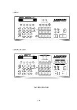
Page 141: ...V 54 FAX3750 FAX 8650P MFC7750 Key Button Entry Order ...
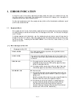
Page 146: ...CHAPTER VI ERROR INDICATION AND TROUBLESHOOTING ...
Page 171: ...Oct 98 SM5X5303 Printed in Japan ...
Page 172: ...FAX3750 FAX 8650P MFC7750 Appendix 1 EEPROM Customizing Codes ...
Page 194: ......
Page 195: ......
Page 196: ......


