


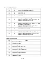

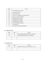


VI
- 15
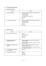
2.
TROUBLESHOOTING
2.1
Introduction
This section gives the service personnel some of the troubleshooting procedures to be followed if
an error or malfunction occurs with the facsimile equipment. It is impossible to anticipate all of the
possible problems which may occur in future and determine the troubleshooting procedures, so
this section covers some sample problems. However, those samples will help service personnel
pinpoint and repair other defective elements if he/she analyzes and examines them well.
2.2
Precautions
Be sure to observe the following to prevent the secondary troubles from happening:
(1)
Always unplug the AC power cord from the outlet when removing the covers and PCBs,
adjusting the mechanisms, or conducting continuity testing with a circuit tester.
(2)
When disconnecting the connectors, do not pull the lead wires but hold the connector
housings.
(3)
l
Before handling the PCBs, touch a metal portion of the machine to discharge static
electricity charged in your body.
l
When repairing the PCBs, handle them with extra care.
After repairing the defective section, be sure to check again if the repaired section works correctly.
Also record the troubleshooting procedure so that it would be of use for future trouble occurrence.
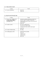
2.3
Checking prior to Troubleshooting
Prior to proceeding to the troubleshooting procedures, check that:
(1)
Each voltage level on AC input lines and DC lines is correct.
(2)
All cables and harnesses are firmly connected.
(3)
None of the fuses are blown.
Summary of Contents for FAX-8650P
Page 1: ...FACSIMILE EQUIPMENT SERVICE MANUAL MODEL FAX3750 FAX 8650P MFC7750 ...
Page 5: ...CHAPTER I GENERAL DESCRIPTION ...
Page 12: ...CHAPTER II INSTALLATION ...
Page 13: ...CONTENTS 1 INSTALLING THE UPDATE DATA TO THE FACSIMILE EQUIPMENT II 1 ...
Page 16: ...CHAPTER III THEORY OF OPERATION ...
Page 18: ...III 1 1 OVERVIEW Not provided on the FAX 8650P ...
Page 28: ...III 11 Not provided on the FAX 8650P Location of Sensors and Actuators ...
Page 31: ...III 14 Main PCB Modem PCB ...
Page 36: ...CHAPTER IV DISASSEMBLY REASSEMBLY AND LUBRICATION ...
Page 42: ...IV 4 n n Disassembly Order Flow ...
Page 71: ...IV 33 1 Provided on the FAX 8650P 2 Not provided on the FAX 8650P ...
Page 72: ...IV 34 Setting up the main PCB after replacement ...
Page 84: ...IV 46 2 Control panel locks 3 Scanner frame ASSY and separation roller gear ...
Page 85: ...IV 47 4 Top cover lock spring 5 Gear drive unit ...
Page 86: ...CHAPTER V MAINTENANCE MODE ...
Page 93: ...V 6 Scanning Compensation Data List ...
Page 141: ...V 54 FAX3750 FAX 8650P MFC7750 Key Button Entry Order ...
Page 146: ...CHAPTER VI ERROR INDICATION AND TROUBLESHOOTING ...
Page 171: ...Oct 98 SM5X5303 Printed in Japan ...
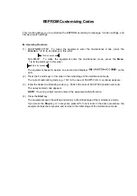
Page 172: ...FAX3750 FAX 8650P MFC7750 Appendix 1 EEPROM Customizing Codes ...
Page 194: ......
Page 195: ......
Page 196: ......


