
DT3-B291
53
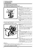
10. STANDARD ADJUSTMENTS
10. STANDARDEINSTELLUNGEN
10. REGLAGES STANDARD
10. AJUSTES ESTANDARES
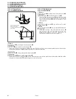
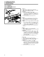
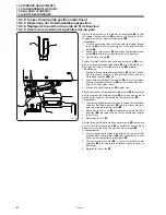
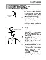
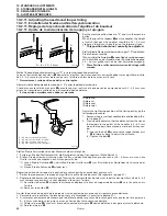
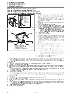
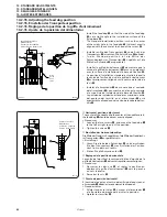
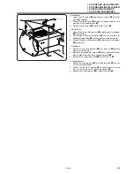
4. Turn the machine pulley to move the loopers
q
for-
ward, and check that the tips of the loopers
q
pass by
the grooves in the needles.
* If the tips of the loopers
q
do not pass by the
grooves in the needles, refer to “10-2-12. Adjusting
the needle and looper positions”.
4. Stellen Sie die Greifer
q
durch Drehen der
Riemenscheibe nach vorne und kontrollieren Sie, ob
die Greiferspitzen
q
sich an den Nadeleinbuchtungen
vorbeibewegen.
* Falls sich die Greiferspitzen
q
nicht in den
Nadeleinbuchtungen vorbeibewegen, wird auf “10-
2-12. Einstellen der Nadel- und Greiferpositionen”
verwiesen.
4. Tourner la poulie de machine pour déplacer les boucleurs
q
vers l’avant, et vérifier que la pointe des boucleurs
q
dépasse la rainure des aiguilles.
* Si la pointe des boucleurs
q
ne dépasse pas la rainure des aiguilles, se reporter à la section “10-2-12. Réglage de
la position de l’aiguille et du boucleur”.
4. Girar la polea de la máquina para mover los ojos-guía
q
hacia adelante, y verificar que las puntas de los ojos-guía
q
pase por las ranuras en las agujas.
* Si las puntas de los ojos-guía
q
no pasan por las ranuras en las agujas, consultar la sección “10-2-12. Ajuste de
la posición de la aguja y el ojo-guía”.
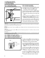
q
0434M
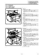
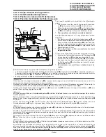
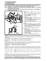
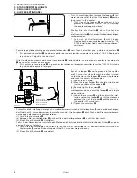
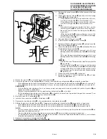
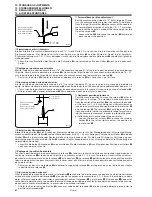
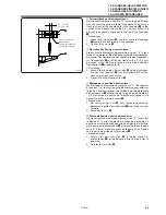
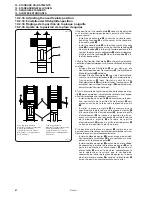
5. Adjust as follows so that the clearance between the
tips of the loopers
q
and the grooves in the needles
are 0.1 mm or less when the machine pulley is turned
so that the tips of the loopers
q
are moving forward
and reach the centers of the needles.
(1) Loosen the screw
r
.
(2) Move the looper holder
e
to the left or right to ad-
just the positions of the loopers
q
.
(3) Securely tighten the screw
r
.
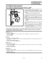
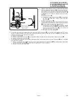
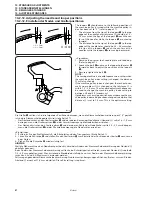
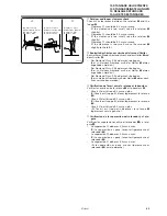
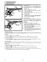
* If the clearance cannot be adjusted correctly by the
method given above, adjust the looper
q
on a single
side as follows.
(1) Loosen the set screw
w
, and then adjust the instal-
lation angle of the looper
q
so that the clearance
between the tip of the looper
q
and the groove in
the needle is 0.1 mm or less.
(2) Tighten the set screw
w
.
5. Führen Sie die Einstellung wie folgt aus, um den Abstand zwischen den Greiferspitzen
q
und den Einbuchtungen
der Nadeln auf 0,1 mm oder weniger einzustellen, wenn die Greiferspitzen
q
durch Drehen der Riemenscheibe nach
vorne gegen die Nadelmitte bewegt werden.
(1) Lösen Sie die Schraube
r
.
(2) Bewegen Sie den Greiferhalter
e
zum Einstellen der Greiferpositionen
q
nach links oder rechts.
(3) Ziehen Sie die Schraube
r
richtig fest.
* Falls sich der Abstand mit der vorstehenden Methode nicht richtig einstellen läßt, stellen Sie den Greifer
q
auf einer
einzigen Seite wie folgt ein.
(1) Lösen Sie die Schraube
w
und stellen Sie den Winkel des Greifers
q
so ein, daß der Abstand zwischen der
Greiferspitze
q
und der Einbuchtung der Nadel 0,1 mm oder weniger beträgt.
(2) Ziehen Sie die Schraube
w
wieder fest.
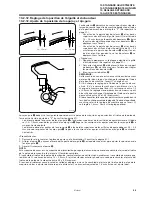
e
w
r
q
0.1 mm or less
0,1 mm oder weniger
0,1 mm ou moins
0,1 mm o menos
0431M
0435M