7. ADJUSTMENTS
SL-710A
70
7-11. Synchronizer Adjustment
The synchronizer uses a single element to detect the
needle up stop position. The needle down single is fixed.
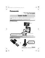
Checking method
1. Turn on the power switch.
2. Stop the machine with the needle in the needle down
position.
Check that the distance from the top of the needle
plate to the bottom edge of the needle set screw is 19
- 25 mm at this time.
3. After the thread is trimmed, stop the machine with the
needle in the needle up position.
4. Check that the distance from the top of the needle
plate to the tip of the needle is within the value shown
in the illustration in accordance with the machine
model.
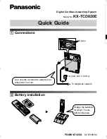
Adjusting the needle up stop position.
1. Turn off the power switch.
2. Loosen the screw (1).
3. Move the screw (1) in the direction of rotation of the
machine pulley to raise the needle bar (2) to a higher
stop position.
Move the screw in the other direction to lower the
needle bar stop position.
4. Securely tighten the screw (1).
Note:
Do not turn the pulley while the screw (1) is
loosened, otherwise other parts may become
damaged as a result of the looseness.
0931M
0741M
0932M
(2)
(1)
19 - 25 mm
Needle down position
Needle up position
<-[][]1>
8 - 10.5 mm
<-[][]3>
10 - 12.5 mm
<-[][]5>
12.5 - 15 mm
Becomes lower
Becomes higher
Summary of Contents for DB2-DD7100
Page 113: ...21 WIRING DIAGRAMS SL 710A 106 Control circuit board assembly 2 6 1934M ...
Page 114: ...21 WIRING DIAGRAMS SL 710A 107 Control circuit board assembly 3 6 1890M ...
Page 115: ...21 WIRING DIAGRAMS SL 710A 108 Control circuit board assembly 4 6 1891M ...
Page 116: ...21 WIRING DIAGRAMS SL 710A 109 Control circuit board assembly 5 6 1892M ...
Page 117: ...21 WIRING DIAGRAMS SL 710A 110 Control circuit board assembly 6 6 1893M ...
Page 136: ...21 WIRING DIAGRAMS SL 710A 129 21 4 Transformer 1912M ...
Page 137: ...21 WIRING DIAGRAMS SL 710A 130 21 5 Operation panel B 40 Operation panel B 40 1 3 1913M ...
Page 138: ...21 WIRING DIAGRAMS SL 710A 131 Operation panel B 40 2 3 1914M ...
Page 139: ...21 WIRING DIAGRAMS SL 710A 132 Operation panel B 40 3 3 1915M ...
Page 140: ...21 WIRING DIAGRAMS SL 710A 133 21 6 Operation panel B 100 Operation panel B 100 1 3 1916M ...
Page 141: ...21 WIRING DIAGRAMS SL 710A 134 Operation panel B 100 2 3 1917M ...
Page 142: ...21 WIRING DIAGRAMS SL 710A 135 Operation panel B 100 3 3 1918M ...