5. DISASSEMBLY
SL-710A
23
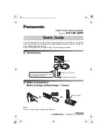
5-13. Bobbin case, rotary hook and thread trimming mechanism
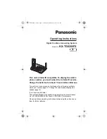
5-14. Feed bar mechanism
5-15. Feed rocker shaft
9
Screw
10
Fixed knife
18
Screw [Loosen]
19
Movable knife holder assy
16
Shoulder screw
15
Knife holder presser plate
14
Screws [3 pcs]
3
Bobbin case
17
Movable knife
holder
13 Movable knife
12
Screws [2 pcs]
4
Screws [3 pcs]
5
Rotary hook
21 Forked shaft
22
Collar
11
Spring [Remove from stud]
20
Spring [Remove]
2
Bobbin case holder position bracket
7
Washer
8
Lower thread finger
6
Screw
1
Screw
13
Movable knife
12
Screws [2 pcs]
Pull the movable knife holder in the direction
of the arrow so that the two pan screws can
be seen from the needle plate side.
1682M
1683M
6
Set screws [2 pcs: Loosen]
7
Feed bracket assy
[Separate]
5
Oil cap
3
Set screws [2 pcs: Loosen]
2
Feed lifting rock bracket stud
[with wick]
4
Feed lifting eccentric wheel assy
1
Set screw [Loosen]
1684M
6
Feed rocker shaft [Pull out from the left]
5
Set screw [2 pcs: Loosen-DD7100]
5
Set screw [2 pcs: Loosen-
DD7100A, 710A]
3
Screw [Loosen]
2
Rubber cap
4
Feed rocker arm [separate]
1
Rubber cap
[Gear box]
8
Washer [Removable]
7
Collar
[Removable]
1685M
Summary of Contents for DB2-DD7100
Page 113: ...21 WIRING DIAGRAMS SL 710A 106 Control circuit board assembly 2 6 1934M ...
Page 114: ...21 WIRING DIAGRAMS SL 710A 107 Control circuit board assembly 3 6 1890M ...
Page 115: ...21 WIRING DIAGRAMS SL 710A 108 Control circuit board assembly 4 6 1891M ...
Page 116: ...21 WIRING DIAGRAMS SL 710A 109 Control circuit board assembly 5 6 1892M ...
Page 117: ...21 WIRING DIAGRAMS SL 710A 110 Control circuit board assembly 6 6 1893M ...
Page 136: ...21 WIRING DIAGRAMS SL 710A 129 21 4 Transformer 1912M ...
Page 137: ...21 WIRING DIAGRAMS SL 710A 130 21 5 Operation panel B 40 Operation panel B 40 1 3 1913M ...
Page 138: ...21 WIRING DIAGRAMS SL 710A 131 Operation panel B 40 2 3 1914M ...
Page 139: ...21 WIRING DIAGRAMS SL 710A 132 Operation panel B 40 3 3 1915M ...
Page 140: ...21 WIRING DIAGRAMS SL 710A 133 21 6 Operation panel B 100 Operation panel B 100 1 3 1916M ...
Page 141: ...21 WIRING DIAGRAMS SL 710A 134 Operation panel B 100 2 3 1917M ...
Page 142: ...21 WIRING DIAGRAMS SL 710A 135 Operation panel B 100 3 3 1918M ...