Brooks
®
Model SLA5840
1-7
Section 1 Introduction
Installation and Operation Manual
X-PR-SLA5840-Series-RevB-RT-eng
Part Number: 541B201AAG
October, 2017
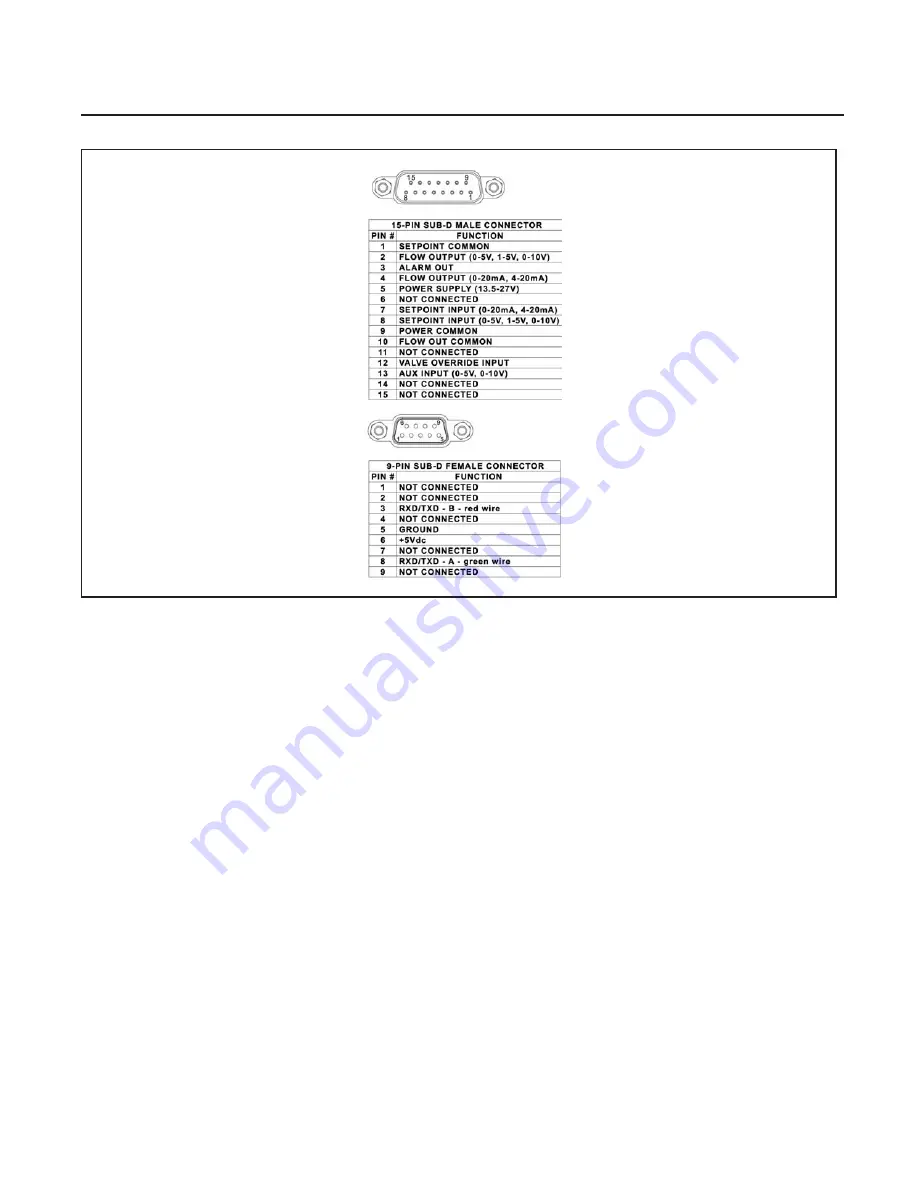
Figure 1-2 SLA5840 Profibus Connections and Pinouts
Profibus
®
Communications
The Brooks SLA5840 is now equipped to support the Profibus communication protocol. Profibus is a fieldbus-
based automation standard of Profibus and Profinet International (PI). Via a single bus cable, Profibus links
controller or control systems with decentralized field devices (sensors and actuators) on the field level and also
enables consistent data exchange with higher ranking communication systems. A 9-pin sub-D connector is
included on every device and is galvanic isolated from the main electronics as defined by the EN 50170 Profibus
standard to allow easy network connection separate from the main connector. The main 15-pin sub-D connector
or termination board is still needed for the power supply, but also allows for the standard analog I/O signals,
analog valve override, and (open-collector) alarm signaling to be used separate from the network connection.
The communication electronics allows for automatic baud rate detection ranging from 9600 baud to 12 Mbaud,
thus making the need for any hardware baud rate selection methods not required. For selecting the device
address, which must be unique on the network, two rotary switches are provided. This allows a user to easily
select any address number ranging from 0 to 126. This can provide fast device replacement without complex
network configurations. The Profibus-DP piggyback board is equipped with a zero command pushbutton, allowing
the user to give a manual command to the device to (re)balance the flow sensor electronics. This command can
also be issued through the protocol.
The Profibus-DP communication option supports the following message types:
• Cyclic data exchange (Write/Read data).
• Read inputs (e.g. status, flow, temperature, totalizer, etc.).
• Read outputs (e.g. commands, setpoint).
• Global control commands (e.g. fail safe, sync).
• Get configuration (i.e. read number of I/O bytes and composition).
• Read diagnostics information (i.e. get error and alarm status).
• Set parameters (i.e. select gas number, engineering units, I/O configuration
• Set parameters (i.e. select gas number, engineering units, I/O configuration etc.).
• Check configuration (i.e. check I/O composition).
Note: Aux Input is used for
Remote Transducer Pressure
Controllers only.


