


DATA CENTER
CONFIGURATION GUIDE
Configuring an iSCSI SAN Using Brocade FCX Switches
9
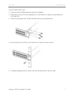
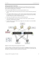
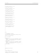
Figure 1.
Connecting Brocade FCX-S switches in a ring topology stack
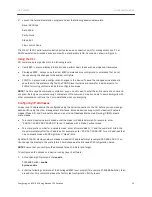
Connecting Brocade FCX-E Switches
NOTE:
Brocade FCX 648-E switches must have a 4-port 10 Gbps SFP+ module (optional) installed to
operate in a stack.
A stack can contain up to eight Brocade FCX-E switches. To connect Brocade FCX-E switches in a stack:
1.
Plug one end of an LC-LC MM Fiber cable into one of the top unit’s SFP+ stacking ports.
2.
Plug the other end of the cable into one of the stacking ports of the next unit.
3.
Repeat steps 1 and 2 for each unit in the stack. Form a simple chain starting with a stacking port on the top
unit and ending at a stacking port on the bottom unit (stacking up to eight units).
4.
(Optional) To form a ring stack topology, plug one end of an LC-LC MM Fiber cable into the remaining
stacking port on the bottom unit and the other end into the remaining stacking port on the top unit.
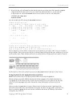
Figure 2.
Connecting Brocade FCX-E switches in a ring topology stack


