


DATA CENTER
CONFIGURATION GUIDE
Configuring an iSCSI SAN Using Brocade FCX Switches
10
Cabling requirements for redundancy
Most iSCSI storage arrays have two storage controllers, with two to four Ethernet ports per controller. At
least two Ethernet ports should be cabled from each of the controllers for redundancy. Each controller is
then connected to multiple switches in the iSCSI SAN.
To build a highly available iSCSI SAN, ensure the following requirements are met:
•
Contains at least two Brocade FCX switches, each with two PSUs, and each PSU uses a separate power
source.
•
For Brocade FCX switches configured in a stack, create two redundant stacks. Each stack is managed
as a logical switch with one active management node. Each switch in the stack should have two PSUs,
and each PSU should be supplied by a separate power source.
•
Ensure there are two separate power sources for each iSCSI storage array.
•
For each iSCSI storage array, ensure there are at least two Ethernet ports on each controller with
connections to multiple switches in the stack.
•
For greater redundancy, each initiator may be configured with multiple adapters or dual-port adapters
to connect to the iSCSI SAN.
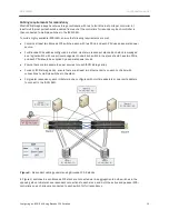
Figure 3.
Redundant cabling example using Brocade FCX-S stacks
In Figure 3, switches in each Brocade FCX stack are connected via link aggregation to both switches in the
opposing stack. Initiators have redundant connections to each stack, and both the active and passive iSCSI
controllers on each array are connected to each switch for full redundancy.


