


DATA CENTER
CONFIGURATION GUIDE
Configuring an iSCSI SAN Using Brocade FCX Switches
8
Cabling
A separate, isolated network should be configured to handle iSCSI traffic for performance and reliability of
the iSCSI SAN. Proper cabling is also necessary to provide redundancy in the iSCSI SAN environment. This
section reviews required cabling practices.
NOTE
: If you only installed one switch, proceed to “Powering On the System” on page 11.
Connecting switches in a stack
NOTE:
If you are creating an iSCSI SAN based on non-stackable switches, skip this section.
The Brocade FCX switch can be stacked to increase the available port count. To stack multiple Brocade FCX
648-S switches, use the dedicated 16Gbps stacking ports found on the rear of each unit, see Figure 1. To
stack multiple Brocade FCX 648-E switches, use the 10 Gbps SFP+ front-facing ports with LC-LC MM Fiber
cables, see Figure 2. Note that Brocade FCX 648-E switches must have a 4-port 10 Gbps SFP+ module
(optional) installed to operate in a stack. Up to eight Brocade FCX switches may be stacked, although a
typical iSCSI solution will not require this many ports.
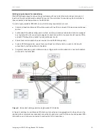
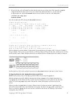
In ring stack topology, an extra cable is connected between the top and bottom switches forming a “ring” or
“closed-loop.” The closed-loop cable provides a redundant path for the stack link, so if one link fails, stack
communications can be maintained. Figure 1 illustrates a ring-topology stacking configuration. In a
redundant iSCSI deployment of stacked Brocade FCX switches, the closed-loop topology should be
deployed.
BEST PRACTICE:
Brocade highly recommends using the ring topology stack. This topology will ensure that all
switches have a redundant path in the stack.
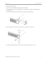
Connecting Brocade FCX-S Switches
A stack can contain up to eight Brocade FCX-S switches. To connect Brocade FCX-S switches in a stack:
1.
Plug one end of a stack cable into one of the top unit’s CX4 stacking ports.
2.
Plug the other end of the stack cable into the next unit’s CX4 stacking ports.
3.
Repeat steps 1 and 2 for each unit in the stack. Form a simple chain starting with a stacking port on the top
unit and ending at a stacking port on the bottom unit (stacking up to eight units).
4.
(Optional) To form a ring stack topology, plug one end of a stack cable into the remaining stacking port on
the bottom unit and the other end into the remaining stacking port on the top unit.
One device in the stack will operate as the Active Controller, one will operate as standby Controller, with
the rest of the units operating as stack members. For information about how to configure your stack,
see the
Brocade FCX Configuration Guide
.
BEST PRACTICE:
If you are approaching the eight-switch stack limitation, contact Brocade for
recommendations on how to effectively scale your iSCSI SAN for the future.


