


DATA CENTER
CONFIGURATION GUIDE
Configuring an iSCSI SAN Using Brocade FCX Switches
7
Power Connection
A secondary power supply provides backup power in case of a failure and for load-balancing when both
power supplies are operational. Load-balancing gives the power supplies a longer life span. The Brocade
FCX PSUs are hot-swappable. In addition, power for each PSU should be routed from two independent
power sources to increase availability. The same power considerations should be made for the servers and
storage arrays.
BEST PRACTICE:
Brocade highly recommends that redundant power supplies be installed in the switch. An
integral component of an effective SAN is reliability. A redundant power supply connected to a separate
source of power ensures no downtime in the event of a circuit failure.
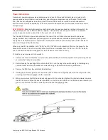
The Brocade FCX has two power receptacles at the rear of the unit. Each device ships with one power
supply installed, and a redundant power supply can be purchased and installed separately. Each power
supply has one standard power receptacle for the AC power cable, and includes AC and DC status LEDs for
easy monitoring and troubleshooting.
When only one PSU is installed, both "AC OK" and "DC OK" LEDs on the installed PSU must be green for the
Brocade FCX device to function normally. When two PSUs are installed, both "AC OK" and "DC OK" LEDs for
one of the installed PSUs must be green for the FCX device to function normally.
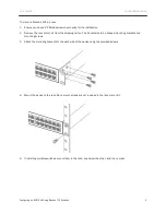
To install a power supply unit in the switch:
1.
Remove the blank metal plate (or a previously installed PSU) from the appropriate slot by removing the two
screws with a flat-head screwdriver.
2.
Before opening the package that contains the PSU, touch the bag to the switch casing to discharge any
potential static electricity. Brocade recommends using an ESD wrist strap during installation.
3.
Remove the PSU from the anti-static shielded bag.
4.
Holding the PSU level, guide it into the carrier rails on each side and gently push it all the way into the slot,
ensuring that it firmly engages with the connector.
5.
When you are sure the PSU has properly engaged with the connector, tighten the retainer screws to secure
the PSU in the slot. When the device is powered on, the AC and DC LEDs on the PSU back panel should turn
green to confirm that the PSU is correctly installed and is supplying power.


