


DATA CENTER
CONFIGURATION GUIDE
Configuring an iSCSI SAN Using Brocade FCX Switches
11
B
ASIC
S
WITCH
S
ETUP AND
C
ONFIGURATION
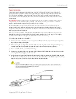
Powering On the System
Once physical installation is complete, perform the following to power on the system:
1.
Remove the power cable from the shipping carton.
2.
Connect the AC power cable to the AC connector on the rear panel.
3.
Insert the power cable plug into a 115V or 120V outlet.
4.
Repeat steps 1-3 for redundant a power supply (if applicable), but connect it to a separate power source.
5.
Repeat steps 1-4 for all switches in the SAN.
NOTES:
•
To turn the system off, simply unplug the power cable or cables.
•
The power outlet should be installed near the equipment, and it should be easily accessible.
•
If the outlet is not rated 115/120V, stop and obtain the appropriate cable for the outlet.
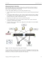
Connecting to a PC or Terminal
To manage the switch, connect the console serial port on the switch to a management station, such as a PC
running a terminal emulation application (for example, HyperTerminal or Putty).
Use the serial connection to perform basic configuration tasks, including assigning an IP address and
subnet mask to the system. This information is required to manage the system using the Web management
interface, IronView Network Manager, or the CLI through Telnet.
To assign an IP address, you must have access to the Command Line Interface (CLI). The CLI is a text-based
interface that can be accessed through a direct serial connection to the device and through Telnet
connections. The CLI is described in detail in the
Brocade FCX Configuration Guide
.
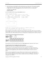
To attach a management station to the console serial port:
1.
Connect a PC or terminal to the serial port of the switch using a straight-through cable. The serial port has a
male DB-9 connector.
Figure 4.
Console serial port (DB-9 DTE) pin-out


