background image

 37 

Treadwall M6 Pro Owner’s Manual—2017 

Main Channel Assembly 

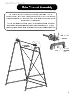
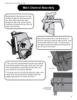
Install the angle-adjuster tube through the holes 
with plastic bushings in the channels. 

The wheel is usually located on the right side of 
the Treadwall, but it can be on either side, 
depending on the location. Make sure there is 
good access to it.  All of the hardware for the 
angle adjuster is located in bag M6-3 

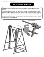
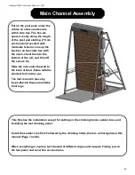
After the cables are installed and working, move 
the assembled Treadwall to its final location 
while it is still light enough to push around. If it is 
on a finished floor, slip rags or hand towels 
under the feet to prevent scratching.  

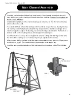
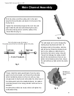
When you first uncoil the cables, you will see that there is a kink in the 
cable. The cables are attached to the tube by hooking this kink under a 
tab cut into the tube near each end (fig. 1). Note that the kink is not in 
the middle of the cable. There is a long end and a short end. 

Attach the cable to the tube (by hooking the kink under the triangular 
tab) with the short end going towards the back. After you wind the 
cable, this end will actually be going towards the front of the machine.  

fig. 1 

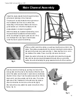
Lock the tube from rotating by pushing one hole of the 
locking disk onto the stud on the channel. Wind the short 
end of the cable onto the tube in neat coils in a clockwise 
direction. Note in fig. 2 how the cable is wound so that the 
short end is near the outside end of the tube. 

This is the 

right side of the Treadwall. On the left side, the cable is 
wound so that the short end is on the inside (fig.5).


After about five coils, attach the cable to the front of the 
frame ( fig. 3).  

fig. 2 

fig. 3 

Summary of Contents for Treadwall M6 Pro

Page 1: ...Treadwall M6 Pro Owner s Manual 87 York Ave Randolph MA 02368 781 961 5200 www brewerfitness com Copyright 2017 Brewer Fitness...

Page 2: ......

Page 3: ...r Treadwall a Success 11 Information for Your Staff 13 Training Tips Guidelines 14 Activities Promotional Ideas 16 Frequently Asked Questions 18 General Maintenance 20 Troubleshooting 22 Service Instr...

Page 4: ...ii Treadwall M6 Pro Owner s Manual 2017...

Page 5: ...signed to help managers staff and trainers take full advantage of this equipment This reference tool emphasizes the benefits of vertical movement with links and resources to help integrate the wall in...

Page 6: ...2 Treadwall M6 Pro Owner s Manual 2017...
Page 7: ...s Manual Provide a general overview of the basic opera ons and usage to new Treadwall users Do not place other equipment or any items in the fall zone or onto the oor mat of the Treadwall M6 Pro Speci...

Page 8: ...4 Treadwall M6 Pro Owner s Manual 2017...
Page 9: ...l move the wall downwards With our auto stop technology if you stop climbing the Treadwall will stop and wait for you The Treadwall will not move unless you are on the wall and climbing upwards You ca...

Page 10: ...r Treadwall installation the wheel that you use to change the angle can be on either the right or left side on the machine To change the angle you first need to disengage the locking ring To do this r...

Page 11: ...00 0 1 2 3 4 5 6 7 8 9 0 Clear Home Screen The home screen shows real time data for a single climb When you pause for 5 seconds the counter will hold your data on the screen until you begin climbing...

Page 12: ...ommend starting with an even spacing of the rungs with little or no deviation from side to side This provides the best platform for simple aerobic training and fast sprinting climbs The Ladder Line is...

Page 13: ...ntire wall and label individual routes with colored pieces of tape If you want to try your own hand at route setting one of the most fun ways to start is to place holds almost randomly with one hold p...

Page 14: ...10 Treadwall M6 Pro Owner s Manual 2017...
Page 15: ...y for most We recommend that a staff person be chosen as the main advocate for the product s introduction period This person might take on the following responsibilities 1 Read through the manual thor...

Page 16: ...12 Treadwall M6 Pro Owner s Manual 2017...
Page 17: ...e or as part of a circuit routine with oth er equipment Customize it to suit YOUR needs and GOALS 1 You should use the equipment yourself Get a first hand look at how the workout makes you feel learni...

Page 18: ...d focus on smooth movement 5 Emphasize the need to move your feet above a certain panel to keep the wall moving Auto stop will automatically stop the rotation as they approach the bottom 6 Tell them t...

Page 19: ...cles on the benefits of climbing etc 2 Refer to our website for full training program ideas and short workouts Climbing is a progressive activity there is a great deal to learn about balance and techn...

Page 20: ...g 1000 feet a day seven days a week it will take a full month For most people it will take the bet ter part of a year Anybody who completes this challenge will come out a different person fitter stron...

Page 21: ...Devil s Tower Wyoming 5267 Mt Katahdin Maine 6288 Mt Washington New Hampshire 7310 Mt Koscivsko high point in Australia 7569 El Capitan Yosemite National Park 8842 Half Dome Yosemite National Park 957...

Page 22: ...ld pattern get repetitious Eventually but it takes much longer that you might expect The Treadwall has no beginning or end and it con nually presents you with new challenges and possibili es It is sim...

Page 23: ...g play equipment and trees For adults climbing on the Treadwall recaptures much of that simple joy and natural vertical movement What kind of bodies does Vertical Movement build Climbing and gymnastic...

Page 24: ...wall will not move when someone is standing and not climbing upwards The sensor for this system is located at the bottom right side of the machine There is a small switch which closes an electric valv...

Page 25: ...ine Maintenance Schedule How to access the inside of your Treadwall The Treadwall wall panels are bolted to a set of chains These two chains form a continuous loop around the top and bottom axles Each...

Page 26: ...djust ment Check and adjust the small switch at the bottom of the right channel Also make sure that unit is plugged in and receiving adequate power Pg 18 Wall is sluggish lighter weights will not pull...

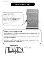
Page 27: ...rnal X bracing adjustment If the internal X bracing is too tight the panels may be restricted in their movement If too loose the wall can sway from side to side For best function the center section of...

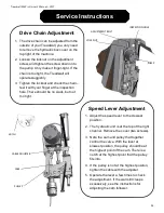
Page 28: ...th your finger at the inspection hole There should be no slack but not too tight CAM PULLEY CABLE ADJUSTER Speed Lever Adjustment 1 Adjust the speed lever to the slowest position 2 The hydraulic unit...

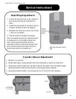
Page 29: ...icroswitch needs to be inspected further or replaced remove the plastic access hole cover and all nuts and washers from the microswitch Reach inside of the access cover and unclip the electrical wire...

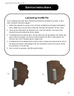
Page 30: ...bricated Two in the front and two in the back Each channel has a rear surface and a front surface 3 To lubricate the rear surfaces fig 1 put the nozzle into the gap between two panels and squirt a lit...

Page 31: ...s Manual Provide a general overview of the basic operations and usage to new Treadwall users Do not place other equipment or any items in the fall zone or onto the floor mat of the Treadwall M6 Pro S...

Page 32: ...o area of a gym Tools required and set up In addition to the tool list you will need a helper and two ladders If you are tight on space begin by assembling the A frames and then bring in the side chan...

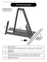
Page 33: ...pper frames 2 Lower Frames The right side has a wire which goes to the rear of the Treadwall 3 Horizontals 4 X brace components The two short pieces and two long pieces are packed with the channels th...

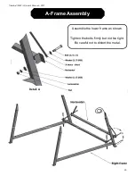
Page 34: ...30 Treadwall M6 Pro Owner s Manual 2017 A Frame Assembly Assemble the lower frame as shown Tighten the bolts firmly but not too tight Be careful not to distort the metal Detail A...

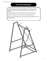
Page 35: ...rough the rear leg up to the top of the frame Be careful not to pinch the wire when assembling the frame Lift the upper frame and slide the back leg together first as shown Do not try to put the front...

Page 36: ...e will be quite shaky Don t stand on any part of the frame until it is completed use ladders Assemble the top horizontal along with the long x brace assemblies Attach the turnbuckles to the short x br...

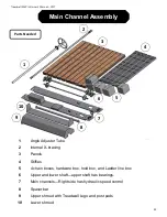
Page 37: ...Tube 2 Internal X bracing 3 Panels 4 Stiffies 5 4 chain boxes hardware box hold box and Ladder line box 6 Upper and lower shaft upper shaft has bearings 8 Spacer bar 7 Main channels Right side has hy...

Page 38: ...round and some of the parts are quite heavy and awkward You should have two 8 foot stepladders and two people for this part of the installation Position your ladders inside the front of the A frame an...

Page 39: ...channel is being put into place The channels particularly the right channel are heavy and require two people When the channel is in place attach it to the square bearing with three flange bolts from b...

Page 40: ...p The bearings are self aligning meaning that they can pivot in their cast iron housings If you need to change the angle of the bearing you can insert a large screwdriver or the handle of a socket wre...

Page 41: ...The cables are attached to the tube by hooking this kink under a tab cut into the tube near each end fig 1 Note that the kink is not in the middle of the cable There is a long end and a short end Atta...

Page 42: ...mmer or piece of wood This will not damage the cable but will stretch them somewhat so that you can tighten the turnbuckle some more Angle the wall all the way back and do the same thing Finally insta...

Page 43: ...ither side of the spacer bar and angle tube one in front and one in back The X bracing slots are located just above the lower rectangular holes and below the square bearings at the top of each channel...

Page 44: ...four small holes below the speed control with the provided screws and nuts The sensor wire and power wire are pre installed and plug directly into the rear of the counter There are three magnets packe...

Page 45: ...e chain but don t make it too tight Too much tension will make the Pushdown Bolt To disassemble the master links use a pair of pliers or a flat blade screw driver to press and slide the retaining clip...

Page 46: ...e tabs fig 1 Bring the other end around the sprockets on the lower shaft Attach the master link When you are doing the second chain be aware that the tabs must be synchronized between the two chains W...

Page 47: ...ertighten the screws If your drill has a clutch use a low setting so that the head of the screw seats down but does not dig into the panel Notice the plastic wear buttons in the corners of the panel T...

Page 48: ...els in the front When this happens insert blocks of 2x4 wood between the bottom panels as shown to jam the wall and prevent it from backing up Use two blocks one at each end of the panels The last thr...

Page 49: ...nt angles and speeds Finally put on the last panel and cover the access holes Put on the post pads under the cables as shown and secure with 4 wire ties The ties are spaced evenly along the length of...

Page 50: ...46 Treadwall M6 Pro Owner s Manual 2017...
Page 51: ...switch is pre set at the factory but it can be adjusted for sensitivity if required by loosening its small mounting screws and pivoting it 4 Check the drive chain at the top of the right channel The...

Page 52: ...48 Treadwall M6 Pro Owner s Manual 2017...
Page 53: ...ch tracks the climbers progress Hold The plastic or wood attachment that a climber uses to hold or stand on Ladder Line A wooden climbing hold that allows for easy and aerobic climbing Mat A foam pad...

Page 54: ...he Treadwall will be free from any defect in materials or workmanship For M4 M6 Kore Commercial models Structural Steel Frames and Welds Ten years parts and labor and freight All other components exce...

Page 55: ...nties implied warranty of merchantabil ity or fitness for a particular purpose is limited in its duration to the duration of the written limited warranties set forth herein b In no case shall Brewer s...

Page 56: ...wall M6 Pro Owner s Manual 2017 Contact Information Website WWW BREWERFITNESS COM Email SALES BREWERFITNESS COM Address Please come by for a visit some time 87 York ave Randolph MA 02368 Phone 1 800 7...

Reviews: