3 7 Heat-Cool Control
3 7 Heat-Cool Control
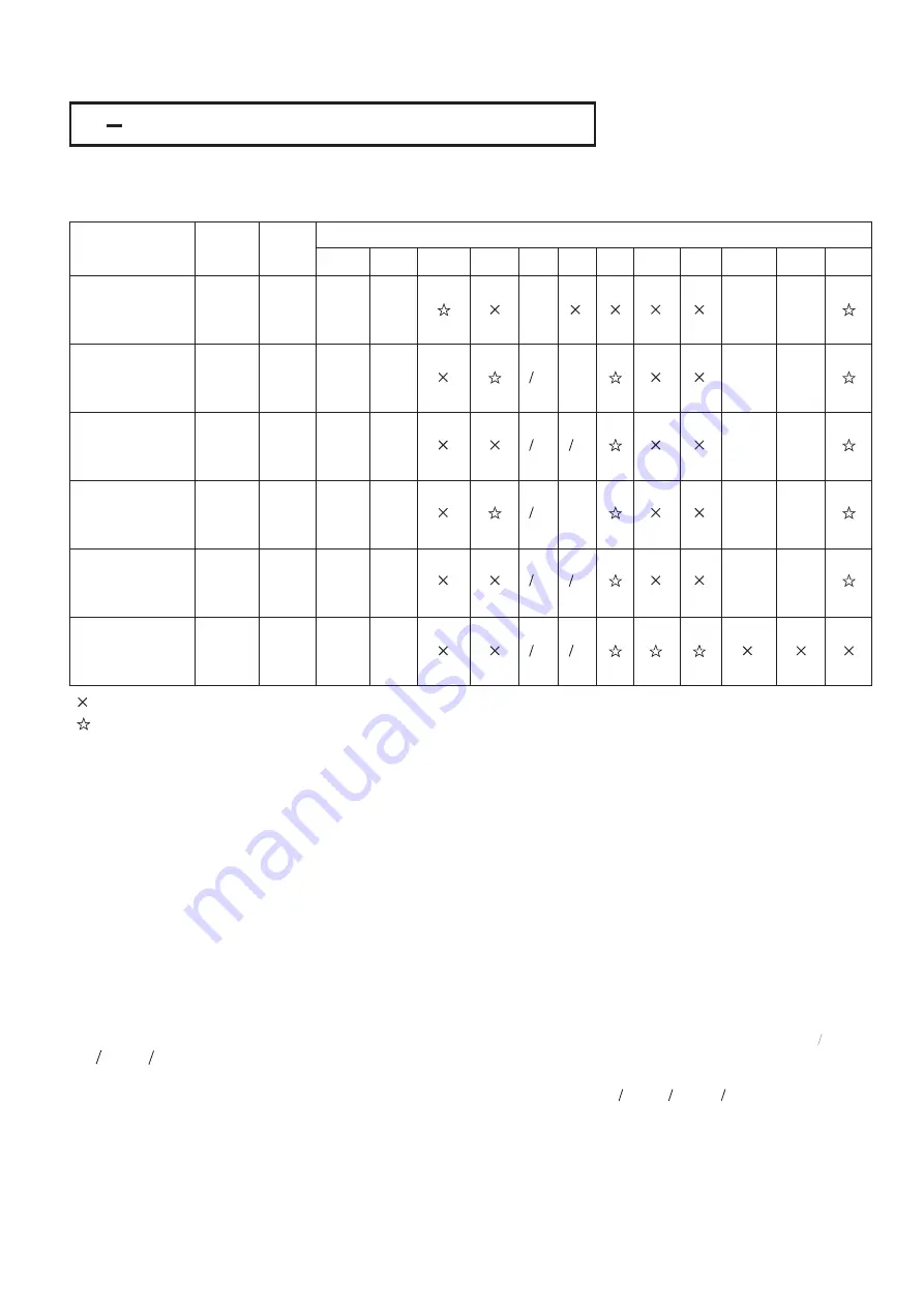
The Heat-Cool Control can use one of
combinations of control modes. Setup of parameters for each control
mode are shown in the following table.
6
The Heat-Cool Control can use one of
combinations of control modes. Setup of parameters for each control
mode are shown in the following table.
6
Control Modes
Heat
Uses
Cool
Uses
Setup Values
OUT1 OUT2 O1HY OFST PB1 TI1
TD1 CPB
A2FN A2MD A2HY
Heat : ON-OFF
Cool : ON-OFF
Heat : ON-OFF
Cool : P ( PD )
Heat : ON-OFF
Cool : PID
Heat : P ( PD )
Cool : ON-OFF
Heat : PID
Cool : ON-OFF
Heat : PID
Cool : PID
OUT1
OUT2
OUT2
OUT1
OUT1
OUT1
OUT2
OUT1
OUT1
OUT2
OUT2
OUT2
REVR
DIRT
DIRT
REVR
REVR
REVR
=AL2
=AL2
=AL2
=AL2
=AL2
COOL
DE.HI
or
PV1.H
DE.LO
or
PV1.L
DE.LO
or
PV1.L
DE.HI
or
PV1.H
DE.HI
or
PV1.H
NORM
NORM
NORM
NORM
NORM
=0
: Don't care
: Don't care
: Adjust to meet process
requirements
: Adjust to meet process
requirements
Table 3.1 Heat-Cool Control Setup
Table 3.1 Heat-Cool Control Setup
NOTE :
Other Setup Required :
The ON-OFF control may result excessive overshoot and undershoot problems in the process. The P ( or PD )
control will result in a deviation process value from the set point. It is recommended to use PID control for the Heat-Cool
control to produce a stable and zero offset process value.
O1TY, CYC1, O2TY, CYC2, A2SP, A2DV
O1TY & O2TY are set in accordance with the types of OUT1 & OUT2 installed. CYC1 & CYC2 are selected according to
the output 1 type ( O1TY ) & output 2 type ( O2TY ).
Generally, selects 0.5 ~ 2 sec. for CYC1, if SSRD or SSR is used for O1TY; 10 ~ 20 sec. if relay is used for O1TY, and
CYC1 is ignored if linear output is used. Similar condition is applied for CYC2 selection.
If OUT2 is configured for ON-OFF control ( by selecting = AL2 ), the OUT2 acts as alarm output, and the process alarm
as well as deviation alarm ( see section 3-9 & 3-10 ) can be used. Adjust A2SP to change set point if process alarm is
used, and adjust SP1 ( with preset A2DV ) to change set point if deviation alarm is used.
Examples:
Heat PID+Cool ON-OFF :
Heat PID+Cool PID :
self-tuning
auto-tuning
manual tuning
Set OUT1= REVR, OUT2= =AL2, A2FN= PV1.H, A2MD=NORM, A2HY=0.1, PB1=0,
TI1=0,TD1=0, and set appropriate values for O1TY and CYC1.
set OUT1=REVR, OUT2=COOL, CPB=100, DB=-4.0, PB1=0, TI1=0 TD1=0, and set appropriate
values for O1TY, CYC1, O2TY, CYC2.
If you have no idea about a new process, then use
program to optimize the PID values by selecting YES for
SELF to enable the self-tuning program .See section 3-19 for self-tuning description. You can use the
program for the new process or directly set the appropriate values for PB1, TI1 & TD1 according to the historical records
for the repeated systems. If the control behavior is still inadequate, then use
to improve the control. See
section 3-21 for manual tuning.
UM25001D
45
DB
=0
=0
=0
=0
=0
=0
=0
=0
=0
=0


