4
WARNING
FOR THE INSTALLER
These instructions should be attached to the
receiver.
VM/100M32 MONITOR
WITH IMAGE STORAGE
This monitor is able to store a maximum of 32
images. It is equipped with the following con-
trols and warnings, figure 1:
Thumb-wheel D to switch the monitor
ON/OFF and for the brightness control,
figure 1.
Button to bring the monitor live and
manual sequencing of any additional
panel/camera.
Button to turn on stairs light.
Door lock release button.
•
Aux 1 - Button for auxiliary services as
required.
Aux 2 - Button for auxiliary services as
required.
LED 1
Green LED can be used to indicate an
external function.
LED 2
Yellow LED can be used to indicate an
external function.
LED 3
Red LED can be used to indicate an
external function.
LED 3 cannot be utilised with the monitor
in the table-top version (VM/
VKT/100).
Time/date select button.
Time/date advance button.
Image save button for automatic image
storage (green LED 4 illuminated).
Recorded image display button.
Recorded image delete button.
Manual image storage button.
LED 4
Green LED, showing automatic image
storage activated by a call from the
entry panel.
Symbol showing the status of green
LED 4 (
= on,
= off) required to
access the functions indicated on the
relevant command button.
There is a data line at the bottom of the screen
showing:
✱
02
18:32
NOV
30
93
year
day
month
cursor
minutes
hours
number of images stored in the memory
when the
✱
symbol appears, the monitor image
is live.
The
symbol means that the image on the
screen is recorded.
•
•
GB
INSTALLATION
INSTRUCTIONS
Switches Aux 1 and Aux 2 are normally open,
when actuated the contacts close on
−
0V DC.
Max. current demand 100mA at 24V.
To activate LED 1, 2 and 3 line 13 and 14
respectively should be connected via an exter-
nal switch device which is common to terminal 5
of the system, 0V DC.
Fuse F1, type T 630mA, located on support’s
printed card, figure 3-5, must be substituted
with fuse F1, type T 1A, supplied with the
monitor.
(Fuse: F = fast, T = slow).
WARNINGS FOR THE USER
- Please do not open or tamper the device (high
voltage!).
- Please avoid knocking or bumping the appa-
ratus as it could result in the breakage of the pic-
ture tube and the consequent projection of glass
fragments.
- In the case of breakdown or modification of
the apparatus of the system (such as power
supplier …) please contact a specialized main-
tenance service.
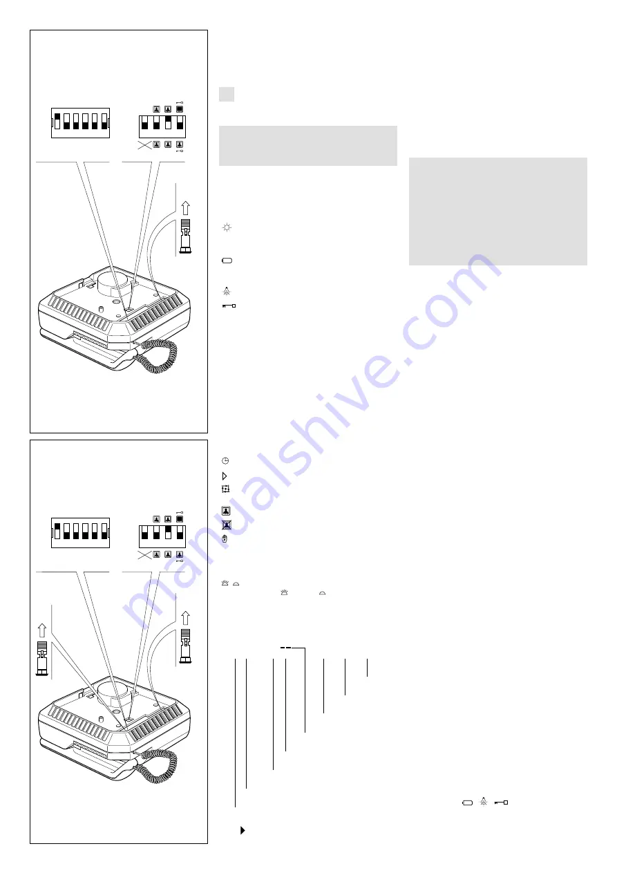
Four special monitor operation modes can be
chosen by means of dip-switches C accessible
from the rear of the monitor. Figure 2 shows
position of dip-switches as supplied.
•
Stand-by mode.
The dip-switch
1
is normally kept in the OFF
position - the stand-by mode is not operating -
the picture appears on the screen in 4 seconds
approx.
In the ON position it activates the stand-by, the
picture appears on the screen almost instanta-
neously.
•
Monitor in constant mode.
For use only in single house installations as
close circuit television system with camera
always powered and separated from entry
panel. VM/100M32 is supplied from the factory
with dip-switch
2
in the OFF position. To pro-
gram the set the dip-switch
2
to ON position
and remove jumper
S,
figure 2. The monitor can
only be switched off by thumb-wheel switch
D
,
figure 1.
•
Activation of more monitors by the same
call.
Dip-switch
3
is normally kept in the ON position,
this way the call line loop is closed. If more
monitors must be activated by the same call,
leave only one with the dip-switch
3
in the ON
position, all other monitors must have the dip-
switch
3
in the OFF position.
Failure to have the dip-switches in the correct
positions will result in the monitors not being
activated.
•
Monitor/system turned off on door release.
a) Systems with VA/100 main control unit.
Dip-switch
4
is normally kept in the OFF posi-
tion. In this position the monitor is turned off
automatically by the system timer. Whit dip-swit-
ch
4
in the ON position the monitor is turned off
by pressing the door lock release button.
b) Systems with VA/100.
01
main control unit.
Dip-switch 4 must be in the OFF position.
Use dip-switch
2
of the VA/100.
01
main control
unit to turn off the monitor.
Call tone
It is possible to regulate the call tone level from
the entry panel by adjusting the trimmer, acces-
sible from the
A
hole placed on the right side of
the monitor, figure 1.
System using main control unit VA/100.
01
has a
timed call feature.
The call stops either when the handset is lifted
or when any
button is pressed.
Personal door-bell
When the personal door-bell is required to be
part of the video entry system, insert the ER/12
C
ON
OFF
1 2 3 4
24h
1
STAND
BY
2
÷
30
60”
STAND
BY
S
1 2 3 4 5 6
ON
OFF
B
10
C
ON
OFF
1 2 3 4
24h
1
STAND
BY
2
÷
30
60”
STAND
BY
S
1 2 3 4 5 6
ON
OFF
R
B
11
IMPORTANTE. Sostituire il fusibile situato
sul supporto con quello fornito con il moni-
tor (F1, T 1A).


