M
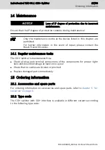
Maintenance................................. 27
Maintenance notes........................ 27
Maximum shock.............................. 8
Maximum temperature gradient..... 7
Maximum vibration......................... 8
Minimum distances....................... 14
MOD........................................ 11, 19
Mounting....................................... 16
Mounting, demounting and
electric installation....................... 14
O
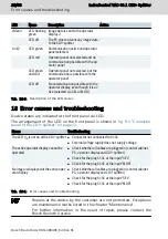
Operating display.......................... 25
Ordering information.................... 27
Overall connection diagram.......... 19
P
Pin assignment
X1S1........................................ 13
Potential equalization................... 20
Power supply unit..................... 6, 18
Power supply unit, external.......... 18
Product identification..................... 3
R
Rear panel mounting..................... 14
Relative humidity............................ 7
S
Safety instructions.......................... 3
Scope of delivery............................ 3
SEL......................................... 11, 18
Service hotline.............................. 29
Shielding....................................... 20
Shielding CDI+ cable.................... 20
Shieling clamps............................. 22
Shock.............................................. 8
Signal alert symbol......................... 4
Signal words................................... 4
Standards....................................... 9
Suggestions.................................... 3
Support........................................ 29
Switching input............................. 13
Symbols.......................................... 5
T
Target groups.................................. 1
Technical data............................... 10
24 V input................................ 10
Degree of protection............... 10
Digital 24 V inputs SEL and
MOD........................................ 11
Weight..................................... 10
Temperature gradient..................... 7
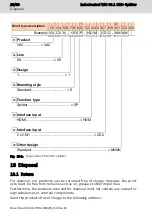
Type code..................................... 27
Type plate....................................... 3
U
UL/CSA certified........................... 10
Use, intended.................................. 5
V
Vibration......................................... 8
Voltage supply............................... 10
W
Warnings......................................... 3
Weight........................................... 10
X
X1S1 assignment.......................... 13
32/33
Index
IndraControl VAC 08.1 CDI+ Splitter
Bosch Rexroth AG R911400465_Edition 01
Summary of Contents for rexroth IndraControl VAC 08.1
Page 1: ...IndraControl VAC 08 1 CDI Splitter Operating Instructions R911400465 Edition 01 ...
Page 6: ...IV IndraControl VAC 08 1 CDI Splitter Bosch Rexroth AG R911400465_Edition 01 ...
Page 36: ...30 33 IndraControl VAC 08 1 CDI Splitter Bosch Rexroth AG R911400465_Edition 01 ...
Page 39: ...Notes IndraControl VAC 08 1 CDI Splitter 33 33 ...


