2
3
4
5
6
11
7
8
9
1
10
12
13
①
24 V mode input, X1S1
②
24 V switching input, X1S1
③
24 V power supply connection, X1S1
④
LED to display the supply voltage, V
IN
⑤
USB connection to the PC for touch and
USB signals
⑥
HDMI input
⑦
Operating state, operator display 1
⑧
CDI+ interface to the first operator dis-
play
⑨
LED for status display of the first con-
nected operator display
⑩
Operating state, operator display 2
⑪
CDI+ interface to the second operator
display
⑫
LED for status display of the second
connected operator display
⑬
Functional earth
Fig. 12-1: Connector panel of the CDI+ splitter
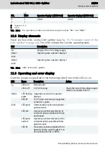
12.1 Function of the digital inputs
SEL
MOD
Operator display 1 (XCDI+tx1)
Operator display 2 (XCDI+tx1)
0
0
Active
-
1
0
-
Active
24/33
Device description
IndraControl VAC 08.1 CDI+ Splitter
Bosch Rexroth AG R911400465_Edition 01
Summary of Contents for rexroth IndraControl VAC 08.1
Page 1: ...IndraControl VAC 08 1 CDI Splitter Operating Instructions R911400465 Edition 01 ...
Page 6: ...IV IndraControl VAC 08 1 CDI Splitter Bosch Rexroth AG R911400465_Edition 01 ...
Page 36: ...30 33 IndraControl VAC 08 1 CDI Splitter Bosch Rexroth AG R911400465_Edition 01 ...
Page 39: ...Notes IndraControl VAC 08 1 CDI Splitter 33 33 ...


