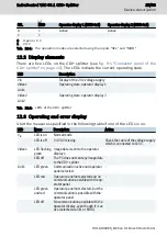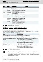
10.5.2 Line lengths and cross-sections
Connection
Cable length
Conductor cross-sections
24 V +
24 V -
30 m max.
1.5 mm
2
(AWG 16)
SEL +
MOD +
SEL/MOD -
100 m max.
0.2 mm
2
to 1.5 mm
2
(AWG 24-16)
Functional earth
1 m max.
6.0 mm
2
(AWG 9)
Tab. 10-1: Cable lengths and cross-sections for the plugs X1S1
Destruction of terminals, insufficient contact
and loss of UL certification if no copper wires
are used.
NOTICE
Use only copper wires to wire the connection terminals.
10.5.3 Connecting 24 V DC
External power supply unit
A 24 V voltage supply supplies the CDI+ splitter.
Use the Bosch Rexroth power supply unit VAP01.1H-W23-024-010-NN (see
ter 5.1 "External 24 V power supply unit" on page 6
). For further information on
the external power supply unit and on the creation of overvoltage categories, re-
fer to the documentation of the power supply unit.
All lines of the 24 V voltage supply have to be routed separately from lines carry-
ing higher voltages.
Destruction of the CDI+ splitter due to connec-
tion under voltage.
NOTICE
Ensure that the PC and the CDI+ splitter are disconnected from voltage before
wiring.
10.5.4 Connecting the digital 24 V inputs SEL and MOD
Digital input SEL
A PLC usually controls this input. Wire the respective PLC output with the input
"SEL" on the CDI+ splitter.
18/33
Mounting, demounting and electric installation
IndraControl VAC 08.1 CDI+ Splitter
Bosch Rexroth AG R911400465_Edition 01
Summary of Contents for rexroth IndraControl VAC 08.1
Page 1: ...IndraControl VAC 08 1 CDI Splitter Operating Instructions R911400465 Edition 01 ...
Page 6: ...IV IndraControl VAC 08 1 CDI Splitter Bosch Rexroth AG R911400465_Edition 01 ...
Page 36: ...30 33 IndraControl VAC 08 1 CDI Splitter Bosch Rexroth AG R911400465_Edition 01 ...
Page 39: ...Notes IndraControl VAC 08 1 CDI Splitter 33 33 ...


