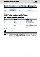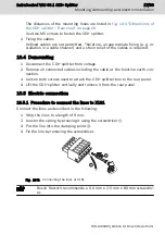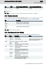
Digital input MOD
A PLC usually controls this input. Wire the respective PLC output with input
"MOD" on the CDI+ splitter.
10.5.5 Connecting the CDI+ interface of the CDI+ splitter to the opera-
tor display
Connect either the XCDI+tx1 connection or the XCDI+tx2 connection to the XCDI
+rx connection of the operator display using an Ethernet cable. Use the cables
listed in
tab. 5-4 "CDI+ connecting cable" on page 6
.
Cable lengths
The connecting cable is available in different lengths.
Use only cables listed in
chapter 5.4 "Connecting cables for the CDI
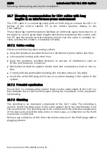
Malfunctions if the CDI+ cable lengths exceeds 100 m.
10.5.6 Connecting the USB interface to the PC
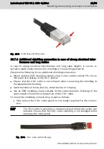
Connect the "XUSB" connection to a USB port of the PC using a USB cable. The
maximum cable length is 3 m. Use this connection to set up the USB connection
between the operator display and the PC.
10.5.7 Connecting the image interface to the PC
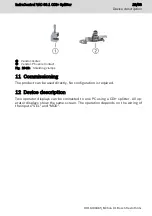
Connect the "XHDMI" connection to the PC using an adapter cable. The maxi-
mum cable length is 3 m. This connection is used to transfer image information
to the operator display.
10.6 Overall connection diagram
PC
24 V switching input
CDI+ splitter
X1S1
USB
display port
XCDI+tx1
XUSB
XHDMI
CDI+
Operator display no. 1
CDI+
Operator display no. 2
24 V voltage supply
XCDI+tx2
Fig. 10-6: Connecting the CDI+ splitter
IndraControl VAC 08.1 CDI+ Splitter
19/33
Mounting, demounting and electric installation
R911400465_Edition 01 Bosch Rexroth AG
Summary of Contents for rexroth IndraControl VAC 08.1
Page 1: ...IndraControl VAC 08 1 CDI Splitter Operating Instructions R911400465 Edition 01 ...
Page 6: ...IV IndraControl VAC 08 1 CDI Splitter Bosch Rexroth AG R911400465_Edition 01 ...
Page 36: ...30 33 IndraControl VAC 08 1 CDI Splitter Bosch Rexroth AG R911400465_Edition 01 ...
Page 39: ...Notes IndraControl VAC 08 1 CDI Splitter 33 33 ...


