background image

5/27 


Bosch Rexroth Canada I March 2021 ı Revision 3.0


Choose 

function 

Valve coil 
PWM 
dither 

Save 
settings 

Blast by distance – Operator can enter a distance for blasting (Future option) 
Momentary blast –


Operator must hold blast button down 

Boot to pause –


Automatically pause the system on boot 

Prewet/liquid interlock -


Prewet and Anti-icing operation interlock with an asymmetrical valve


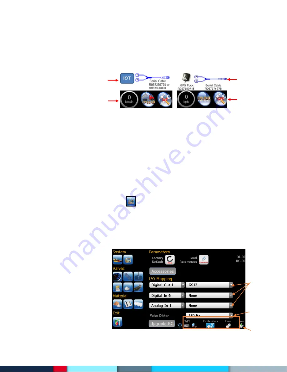
IOT tracking –


Enable AVL interface (default is GPS) 


4 Knob Console –


Enable external 4 knob console 

Eq Rates –


Define only start and end rate as well as increment


CRS blast on –


Turn on cross conveyor blast 

Save last knob –


Remember the knob positions when powering off then on again 

Voice disabled –


Turn off voice feedback 

Volume adjust –


Allow operator to adjust volume 

Summer Mode –


Enable summer mode 

Default Joy Screen –


Always show joystick screen


Enable Profiles –


Enable the use of profiles


Allow sim deice –


Allow prewet to operate separately from conveyor to provide anti icing


Under app solid off –


Turn off solid under application warnings 

Under app prewet off  –


Turn off prewet under application warnings 

Under app deice off –


Turn off deice under application warnings 


12.


Press the secondary options icon           to access additional setup parameters. All additional IOs can be 
set up by using the drop down menus in the I/O mapping section. The drop down fields on the left let 
you pick an input or output (digital or analog), and the drop down directly to the right is the function of 
that particular I/O port. For example, you can select “Analog In 2” on the left, and on the right you can 
select “Temperature” to assign that controller input to be connected to a temperature sensor.  Refer to 
the Special Features with IO mapping section. 

Note: the RC controller wiring must match what is chosen here. 


GPS 
Cable 
 
 
Operator 
screen 

IoT 

Cable 


Operator 

screen 

Summary of Contents for Rexroth CS660

Page 1: ...CS660 CS661 Spreader Controller Calibration Manual ...

Page 2: ... 9 2 5 Material Setup and Calibration 11 2 5 1 Solid Material Setup 11 2 5 2 Solid Material Calibration Manual or Readback Gate 11 2 5 3 Solid Material Calibration Auto Gate 12 2 5 4 Prewet and Anti icing Material Setup 15 2 5 5 Prewet and Anti icing Material Calibration 15 2 6 Material Catch Test 16 3 Set up for additional feature functions 17 3 1 Conveyor Forward and Reverse 17 3 2 Spinner Forwa...

Page 3: ...up the system System Truck Info operation options operator access level temp sensor error severity Sensors Valves Configure all sensors and valve settings Materials Set up and calibrate all solid and liquid materials Joystick If joystick function is enabled set up and calibrate all modes and axis ...

Page 4: ...ptions see Option Checkboxes in this manual 7 Set the items that the user has access to optional 8 Set Blast Timer 0 timer disabled optional This should be set less than Err01 delay 9 Set Percentage of Temp compensation when there is a 3 degree change optional 10 Set the vehicle speed alarm optional 11 Select auxiliary options check marks Press here to enter program mode If Icon is not colored the...

Page 5: ...w joystick screen Enable Profiles Enable the use of profiles Allow sim deice Allow prewet to operate separately from conveyor to provide anti icing Under app solid off Turn off solid under application warnings Under app prewet off Turn off prewet under application warnings Under app deice off Turn off deice under application warnings 12 Press the secondary options icon to access additional setup p...

Page 6: ...s WiFi Screen Calibration Time 13 Click on WiFi network icon to set up WIFI connection The WiFi setup is almost identical to standard Windows Uncheck Notify me to stop this window from popping up every time the system starts up Click Connect and enter Network key Click on LAN IP address icon to configure LAN and assign an IP address LAN IP Address WiFi Network keyboard show hide NOT USED WiFi Setu...

Page 7: ...n the right so you are back to the setup screen Press and hold the WiFi network icon for 5 seconds to clear any preferred networks Now you can perform the WiFi setup Note Any changes to WiFi Network settings Time Screen recalibration need to be saved by clicking the save icon on the bottom of the screen 2 2 Input and Output Configuration To configure appropriate inputs or outputs press the additio...

Page 8: ...A Off CRS cross conveyor on off Re circulation Flush Body Up Plow Down Wing Down Gate In Low Oil Pause Blast Liquid Lvl L R Dump Limit Air Gate PTO Enable Vehicle Reverse Re Activate 1 Re Activate 2 Digital Inputs Aux DigIn1 8 L1 4 Light Outputs 2 2A L5 8 Light Outputs 3 5A Digital Out GS12 When there is ground speed Pause When spreading paused ConveyorRvs When Reverse Button being pushed Boom Lef...

Page 9: ...ed is preferred for more precise speed calibration 2 4 Valve Sensor Setup 1 Tap the icon for the function you with to null 2 Select the control mode Spinner Manual default Half Lane One Lane Conveyor Auger Auto default Open LP Man Spd Manual Prewet Off Fixed V Flow default Manual Manual SPD Return Oil Open Loop Anti Icing Anti icing Off default 1 Boom 3 Boom Manual 3 Set correct conveyor sensor pu...

Page 10: ...be shown in the Min output Max output text boxes 3 Please check the Min null value to verify it is minimum 5RPM Do this by pressing on the Min output value conveyor will start to turn Press again to stop Manual Nulling 1 Press Min value field to pop up the UP DN arrows and enter into edit mode 2 Use up and down arrows to adjust speed so that the motor just begins to turn 3 Press the Min value fiel...

Page 11: ...e Gate position used for material calibration 2 5 Material Setup Calibration 2 5 1 Solid Material Setup Tap on the solid material icon to configure materials desired It allows to set up to 4 different solid materials and 9 application rates and a blast rate for each material 2 5 2 Solid Material Calibration Manual or Readback Gate 1 Prepare a container to catch material discharged 2 Make sure that...

Page 12: ...0lbs material more for better resolution Enter weight of the material collected Continue to next step Stop to abort 2 5 3 Solid Material Calibration Auto Gate 1 Prepare a container to catch material discharged 2 Make sure that sufficient material in the hopper and the system is safe to run 3 Press START to proceed and follow the instruction on the screen Auto Gate operation has two calibration poi...

Page 13: ...u have a container ready and sufficient material always above the gate opening throughout the calibration process Continue to next step Stop to abort STEP 3 Controller automatically move the gate to position 1 Continue to next step Stop to abort STEP 4 Recommend to discharge minimum 100kg or 220lbs material more for better resolution Enter weight of the material collected Continue to next step Sto...

Page 14: ...on 3 Continue to next step Stop to abort STEP 6 Recommend to discharge minimum 100kg or 220lbs material more for better resolution Enter weight of the material collected Continue to next step Stop to abort Complete When the material calibration ends both Wt Revs at calibrated gate position 1 and 3 are refreshed ...

Page 15: ...r ready and sufficient liquid throughout the calibration process 2 5 4 Prewet and Anti icing Material Setup Tap on the prewet material icon or anti ice material icon to configure materials desired It supports 4 prewet and 4 anti ice materials and 9 application rates and a blast rate for each material 2 5 5 Prewet and Anti icing Material Calibration 1 Prepare a container to catch liquid discharged ...

Page 16: ...Continue 2 6 Material Catch Test 2 6 1 Solid Material Catch Test 1 Tap on solid prewet or anti icing icon to enter into the material calibration screen 2 Place an adequate catch container under the spreader discharge chute 3 A wt rev kg rev or lb rev will be calculated and displayed on the bottom right of the screen 4 Repeat this procedure for all solid materials use the left and right arrows to s...

Page 17: ...Box V1 B Conveyor Forward Junction Box V1 A Conveyor Reverse Note When setting up conveyor valve only forward output needs to be trimmed since both Conveyor forward and Reverse outputs share the same Min Max null values 3 2 Spinner Reverse This feature supports bi directional spinner operation It requires a digital input to toggle the direction of the spinner motor Once an input is configured for ...

Page 18: ...e Junction Box V2 B Spinner Forward Junction Box V2 A Spinner Reverse 3 4 3Boom Anti ice DLA This configuration is a dedicated 3 Boom Anti ice system It requires 3 digital inputs junction box or CANIO board and 3 digital outputs for boom control To configure valve outputs it is highly recommended to use AUTONULL 3 5 Dual Spinner This feature supports a single or dual spinner operation It requires ...

Page 19: ...to monitor the air cylinder position When the input status changes the controller switch between 1st and 3rd solid and prewet materials and also set operation gate position to calibrated gate position for the material selected 3 7 Gate Readback and Automatic Gate Gate Readback Automatic Gate It requires a gate sensor to measure It requires a gate cylinder with a the current gate position sensor to...

Page 20: ...top to end the calibration and save calibration value 3 9 4 knob Spreader 1Boom Anti ice This configuration utilizes a 4 knob console and control a spreader spinner conveyor prewet and a 1boom anti ice simultaneously Steps to set up Move gate to max opening Press Max value to highlight Record sensor position Set max gate height Press Max value again to save Move gate to min opening Press Min value...

Page 21: ...tputs it is highly recommended to use AUTONULL functions with sensors 3 11 4 knob Spreader Cross Conveyor This configuration utilizes a 4 knob console and controls a spreader and a cross conveyor simultaneously It requires a digital input to switch cross conveyor direction Left Right 3 12 4 knob Spreader 3Boom Anti ice Cross Conveyor This configuration utilizes a 4 knob console and controls a spre...

Page 22: ...Set up Profiles Profiles allow the operator quick selection of different system configurations One example could be a profile called Standard used for typical spreading operation and another called DLA for dedicated anti icing applications These are only examples and any configuration made in settings can be saved as a profile STEP 1 Check Enable profiles and set 4th Driver to USER see screens bel...

Page 23: ...ctivated once stick returns to neutral OPTION LIST No Prox No prox sensor PFloat2 2nd P flt On Off DmpLmt On Off Emg Interlock Puts conveyor in pause once EMG button is pressed pushed Msg Flash Flash message when dump limit prox is triggered Msg Rst Message disappears once acknowledged till it is triggered again Msg Off Msg disabled Click to START 5 Set up Joystick Operation A typical spreader sys...

Page 24: ...ct joystick slowly until the hydraulic actuator moves press Min while the stick is deflected 5 Move the joystick until the actuator moves at a safe maximum speed press Max 6 Repeat this for all axis directions and modes 7 While in calibration users also have option to double click on any direction arrow to pop up fine tuning screen or click on Stop button again to save all changes ...

Page 25: ... between RC and Joy 1 26 NO JOY2 CHK CONNECTION 26 Comm failure between RC and Joy 2 27 NO GATE POS SENSOR 27 Check gate sensor cable break 28 GATE CLOSED 28 Gate closed in READBACK mode 29 NO SIMULATE 29 Speed Simulation mode stopped 30 SPN UNDER APP 30 Spinner not able to reach desired RPM 31 SOLID UNDER APP 31 Rate or spd too hi incorrect calib 32 PREWET UNDER APP 32 Rate or spd too hi incorrec...

Page 26: ...ormation message to indicate that ground speed simulation mode has been stopped Error 30 Spinner Under Application Desired RPM can not be achieved Check spinner min max outputs and recalibrate spread width Error 31 Solid Under Application Desired RPM can not be achieved Possibly caused by too high application rate or too high ground speed or incorrect calibration Error 32 Prewet Under Application ...

Page 27: ... load parameters from an existing parameter file on the USB stick Load and Retrieve parameters 1 Tap on toolbox icon to pop up tool window in PROGRAM mode 2 Tap on Load Parameters 3 Select a file from the popup file window to load 4 Click on the Select or Cancel button to select or cancel 5 With joystick option users would be given option to keep existing joystick setup 6 Tap OK to reboot 7 Turn t...

Page 28: ......

Page 29: ......

Page 30: ......

Page 31: ......

Reviews: