background image

PSU 5000 / PSG 3000

Instructions for Assembly and Operation

1070 078 224--- 109

Summary of Contents for PSG 3000 Series

Page 1: ...PSU 5000 PSG 3000 Instructions for Assembly and Operation MF Welding Inverters 109 Version ...

Page 2: ...78 224 109 98 10 GB DIN ISO 9001 Reg no 16149 01 2 E 1996 1997 1998 This manual is the exclusive property of ROBERT BOSCH GMBH also in the case of Intellectual Property Right applications Without their consent it may not be reproduced or given to third parties Discretionary charge DM 20 ...

Page 3: ......

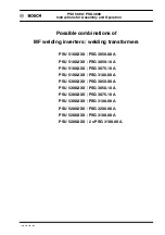
Page 4: ... welding transformers PSU 5100 XXX PSG 3050 00 A PSU 5100 XXX PSG 3050 10 A PSU 5100 XXX PSG 3075 10 A PSU 5100 XXX PSG 3100 00 A PSU 5300 XXX PSG 3050 00 A PSU 5300 XXX PSG 3050 10 A PSU 5300 XXX PSG 3075 10 A PSU 5300 XXX PSG 3100 00 A PSU 5200 XXX PSG 3200 00 A PSU 5200 XXX PSG 3100 00 A PSU 5200 XXX 2 x PSG 3100 00 A ...

Page 5: ...PSU 5000 PSG 3000 Instructions for Assembly and Operation 1070 078 224 109 ...

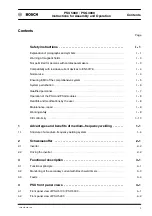
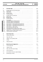
Page 6: ...ualified personnel I 7 Operation of the PSU and PSG modules I 8 Retrofits and modifications by the user I 8 Maintenance repair I 9 Working safely I 9 CE conformity I 10 1 Advantages and benefits of medium frequency welding 1 1 1 1 Structure of a medium frequency welding system 1 4 2 Schweisskoffer 2 1 2 1 Inverter 2 2 2 2 Driving the inverter 2 2 3 Functional description 3 1 3 1 Functional princip...

Page 7: ... 5 5 3 5 PSU 5100 XXX PSU 5300 XXX and PSG 3050 10 A 5 6 5 3 6 PSU 5100 XXX PSU 5300 XXX and PSG 3075 10 A 5 7 5 3 7 PSU 5100 XXX PSG 3100 00 A 5 8 5 3 8 PSU 5200 XXX and PSG 3200 00 A 5 9 5 3 9 PSU 5200 XXX and 2 x PSG 3100 00 A parallel 5 10 5 3 10 PSU 5200 XXX PSU 5300 XXX and 1 x PSG 3100 00 A 5 11 5 3 11 Example of PSU 5100 XXX and PSG 3100 00 A 5 12 5 3 12 Current resistance characteristics ...

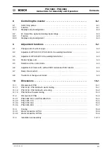
Page 8: ...welding transformer 9 3 9 4 Diode change over 9 3 9 5 Selection of the control mode 9 3 9 6 Adjustment to timers with without KSR module and SSU function 9 4 9 7 Ramp time constant 9 4 9 8 Transformer change over board 9 5 10 Dimensions 10 1 10 1 Dimensions of PSU 10 1 10 1 1 PSU 5100 PSU 5300 with water cooling 10 1 10 1 2 PSU 5100 PSU 5300 with air cooling 10 2 10 1 3 PSU 5200 with water cooling...

Page 9: ...e 11 5 11 2 5 Connection of X21 interface 11 6 11 2 6 Connection of X22 interface 11 6 11 3 PSU mains connection and PSG power connection for nominal operation 11 7 11 4 Connection between PSU and timer module 11 8 11 5 Connection between PSU and PSG 11 10 11 6 Protective conductor connection to medium frequency transformers 11 11 11 7 Parallel connection of 2 PSG s to PSU 5200 11 16 12 Activation...

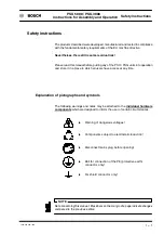
Page 10: ...peration and store it in a place to which all users have access at any time Explanation of pictographs and symbols The following warnings and notes may be attached to the individual hardware components which are designed to inform the user of certain circumstances Warning of dangerous voltages Components subject to electrostatic induction Disconnect mains plug before opening Bolt for connection of...

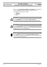
Page 11: ...G The term WARNING will be used wherever danger is imminent The possible consequences may be death or severe injury personal injury ATTENTION The term ATTENTION will be used wherever a dangerous situation is possible The possible consequences include death severe or light injury personal injury damage to property or environmental hazards NOTE The term NOTE will be used for making recommendations o...

Page 12: ...his case additional work protection measures must be taken So far no problems have been reported Nevertheless the possible influences are lower with medium frequency welding than with AC welding Not permitted for persons with cardiac pacemakers WARNING for persons with cardiac pacemakers Warning signs should be posted for protecting persons with cardiac pacemakers because the function of these dev...

Page 13: ...y of 1 kHz 1 2 kHz Normal use The PSU medium frequency welding inverter in connection with the PSG trans former rectifier unit serves for resistance welding of metals using rectified secondary current at the welding current transformer The medium frequency welding equipment is only suitable for industrial applications Definition in accordance with DIN EN 50082 2 of Electromagnetic Compatibility EM...

Page 14: ...dential areas 30 m safe clearance to communication systems wireless telephone 10 m cable length of mains feeder PSU 10 m interference suppression measures When switch cabinet doors are open radio devices and cell phones may only be used in a safe clearance of 2 m The assessment and certificate of conformity of a competent authority concer ning compliance with the fundamental EMC protection is avai...

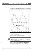
Page 15: ...d mains current bottom in one phase during the welding process Typical 300 Hz The 5th 7th 11th 13th 15th and 17th harmonic wave are the characteristic har monics of the mains current curve The harmonic component depends on the welding power NOTE We recommend operating the welding inverter on a separate welding mains sys tem The harmonic content may be considerably reduced e g by using smoothing re...

Page 16: ...ommission earth and label electrical cir cuits and equipment systems in compliance with the standards of safety technology operating personnel who have been instructed in operating installations in re sistance welding technology and who know the contents of the present docu mentation as far as operation is concerned WARNING An exception are persons with cardiac pacemakers Due to the strong magneti...

Page 17: ...ons are complied with The risk of bruises can be considerably reduced by means of e g two handed start guard rails light barriers etc NOTE Damage to property through inappropriate or insufficient cooling of the modu les Water cooled PSU and PSG modules may only be operated when the cooling water circuit is active Condensation is not permitted on water carrying compo nents The temperature in the in...

Page 18: ...eries Batteries must not be opened forcefully recharged soldered at the cell body or thrown into fire Replace empty batteries with new ones only ATTENTION The right to perform repair maintenance work on the timer compenents is re served to the BOSCH service department or to repair maintenance units autho rized by BOSCH Only use spare parts replacement parts approved by BOSCH Spent batteries or acc...

Page 19: ...ect to the Low Voltage Directive only Concerning EMC it is always necessary to consider the entire application cf below The CE label for the PSS PSU PSG combination is valid for industrial applica tions For other combinations applications the certificate must be derived from the above or a new certificate must be issued if necessary by the line designer user cf also section 16 ...

Page 20: ...cy Inverter out put voltage Welding current Comparison of 50 Hz and medium frequency welding t 1 ms t t U 1000 Hz A direct current flows in the secondary welding circuit of the transformer As a result the inductive resistance of the secondary window loses its influence on the welding current with different immersion depths of the electrode gun into the workpiece The weight of the welding transform...

Page 21: ...welding aluminium and galvanized sheets Especially suitable for 3 sheet welding very thin sheets and fine spot applica tions Fewer welding splashes Welding of different sheet types conventional 50 Hz weld kA ms splash limit bonding limit galvanized sheet bare sheet Welding of galvanized sheet types with 1 kHz welding process kA ms safe splash limit safe bonding limit remaining setting range possib...

Page 22: ...he weld time and helps to obtain a constant welding result The Bosch PSU PSG MF welding system is equipped with an integrated cur rent control 3 Block diagram of a medium frequency welding system Current feedback from transformer rectifier unit Current control by inverter Current control by timer PSS PSU 5XXX PSG 3XXX Enhanced application range for micro welds The inverter has a DIP switch bank fo...

Page 23: ...00 Instructions for Assembly and Operation Advantages Benefits 1070 078 224 108 1 4 1 1 Structure of a medium frequency welding system PSS 5000 PSU 5000 Welding gun PSG medium frequency transformer 1 kHz Mains system ...

Page 24: ...ith interfaces for medium fre quency and 50 Hz applications The weld timer is driven by parallel e g PLC or serial e g bus systems depending on its I O configuration Medium frequency inverter The medium frequency inverters in air or water cooled design are supplied with operating voltages of 400 V to 690 V 50 60 Hz A current range between 3 kA and 18 kA can be used duty cycle depends on cooling an...

Page 25: ... with integrated current control fault diagnostics through seven segment display and BCD code The heat sinks can be optionally mounted at the rear or side panel The inverters are plugged onto four guide pins and fixed by quick action clamps for easy service and replacement 2 2 Driving the inverter The inverter is driven in the Schweisskoffer by PSS 5000 weld timer in 50 Hz or milliseconds design P...

Page 26: ...he welding parameters the inverter is controlled by a weld timer with a 5 kHz weld output cycle As an option it may alsobe controlledby a24 Vweld time signal and an analog input voltage 1 10V for both control options see Sec tion 8 Controlling the inverter The 3 phase 50 60 HZ mains AC is first rectified by a bridge connected rectifier B6 connection The direct current thus generated connects a tra...

Page 27: ... 078 224 108 3 2 The following figure shows a block diagram of an inverter system PSU PSG mains L1 L2 L3 transistorized trans former rectifier direct current link circuit 6 pole bridge rectifier analog controller power supply driver Rectifier Welding trans former PSG sensors Weld timer ...

Page 28: ... displayed through the weld timer and a programming unit equipped with the KSR option Thus it is possible to monitor welding current tolerance limits Using the calibration function the measured welding current can be adjusted to your standardized ammeter and the current setpoint can be entered accordingly Programming the current tolerance is described in a separate Technical Informa tion KSR DYD D...

Page 29: ...ge to property through missing or false interpretation of fault messages If the inverter is not controlled by a Bosch timer it must be ensured that closing of the floating contact between terminals 4 and 5 or opening of the contact between terminals 5 and 10 of connector X5 on the inverter will stop the timer When the cause of the fault has been eliminated the fault message must first be reset wit...

Page 30: ...trode voltage X21 Plug in terminal Ext reset ext enable fault code to PLC internal volt age supply output 24 VDC max 2A X5 Plug in terminal System connection to timer unit X12 Plug in terminal Current feedback to timer unit with SSU operation input for analog command value X22 Plug in terminal Input for weld time 24 V I O supply output for controlled fan Shield connection for X11 and X12 Diagnosti...

Page 31: ... points internal DIP switches S1 S2 S3 and slot for future options X5 Plug in terminal System connection to timer unit Shield connection for X11 and X12 X11 Plug in terminal Connection of PSG sensors for temperature measuring coil signal electrode voltage Output terminals to PSG U V Water connection inlet and outlet X12 Plug in terminal Current feedback to timer unit with SSU operation input for a...

Page 32: ...current control is used With primary current control a continuous current can be applied PSG 3200 00 A current range 6 to 40 kA refer to section 11 Electrical connection PSG 3100 00 A current range 3 to 18 kA PSU 5300 6 to 36 kA PSG 3050 xx A current range 3 to 18 kA PSG 3075 00 A current range 3 to 18 kA Transformer 1 Transformer 2 Transformer 3 Transformer 4 Transformer 5 PSU 5300 Output power C...

Page 33: ...lass Humidity Air pressure Corrosion water 4 l per min max 30û C p max 1 bar water connection through M16x1 5 external thread with taper steps to DIN EN 560 PSU 5200 Installation in switch cabinet with protection class IP54 note PSU power loss vertically installation on switch cabinet mounting plate 0 ûC to 55 ûC with prescribed cooling 25ûC to 70ûC when water cooled Heat sink must have been drain...

Page 34: ...duty cycle 6 3 V 8 4 V 9 0 V 13 0 V 5 2 2 Mechanical data 14 kg 16 kg 25 kg 40 kg see dimension drawing sec 10 2 1 see dimension drawing sec 10 2 1 see dimension drawing sec 10 2 2 see dimension drawing sec 10 2 3 see dimension drawing sec 10 2 4 PSG 3050 00 A PSG 3050 10 A PSG 3075 10 A PSG 3100 00 A PSG 3200 00 A Weight approx Connections mechanical and electrical connections as for standard tra...

Page 35: ...s up to 40 kA can be attained The no load voltage is 14 Volts NOTE Danger of damage to property through inadmissibly high welding current You should therefore check the load diagrams in order to determine whether the maximum welding current of your application is within the admissible ranges The modules should only be operated with appropriate cooling cf also Section 10 3 The load diagrams define ...

Page 36: ... accordingly For comparing different inverters it will not be sufficient to verify the peak current e g 20 kA instead the respective continuous loads have to be compared 5 3 4 PSU 5100 XXX PSU 5300 XXX and PSG 3050 00 A Diode integration time 2 s PSG integration time 60s Limitation by transformer and PSU Limitation by diodes with 50 cycles weld time Limitation by diodes with 20 cycles weld time Li...

Page 37: ...e 60s Limitation by transformer and PSU Limitation by diodes with 50 cycles weld time Limitation by diodes with 20 cycles weld time Limitation by diodes with 10 cycles weld time Limitation by diodes with 5 cycles weld time The load curves represent ab solute limit values For a re liable continuous operation we recommend utilizing these limit values by no more than 80 ED duty cycle Isec kA ...

Page 38: ...e 60s Limitation by transformer and PSU Limitation by diodes with 50 cycles weld time Limitation by diodes with 20 cycles weld time Limitation by diodes with 10 cycles weld time Limitation by diodes with 5 cycles weld time The load curves represent ab solute limit values For a re liable continuous operation we recommend utilizing these limit values by no more than 80 ED duty cycle Isec kA ...

Page 39: ...tion by transformer and PSU Limitation by diodes with 50 cycles weld time Limitation by diodes with 20 cycles weld time Limitation by diodes with 10 cycles weld time Limitation by diodes with 5 cycles weld time Isek kA The load curves represent ab solute limit values For a re liable continuous operation we recommend utilizing these limit values by no more than 80 ED duty cycle Isec kA ...

Page 40: ...Limitation by transformer and PSU Limitation by diodes with 50 cycles weld time Limitation by diodes with 20 cycles weld time Limitation by diodes with 10 cycles weld time Limitation by diodes with 5 cycles weld time The load curves represent ab solute limit values For a re liable continuous operation we recommend utilizing these limit values by no more than 80 ED duty cycle Isec kA ...

Page 41: ...n time 60s Limitation by transformer and PSU Limitation by diodes with 50 cycles weld time Limitation by diodes with 20 cycles weld time Limitation by diodes with 10 cycles weld time Limitation by diodes with 5 cycles weld time The load curves represent ab solute limit values For a re liable continuous operation we recommend utilizing these limit values by no more than 80 ED duty cycle Isec kA ...

Page 42: ... Limitation by diodes with 20 cycles weld time Limitation by diodes with 10 cycles weld time Limitation by diodes with 5 cycles weld time 40 35 30 25 20 15 10 5 1 0 10 100 0 100 200 300 400 500 600 700 800 Isek kA Diode integration time 2 s PSG integration time 60s ED The load curves represent ab solute limit values For a re liable continuous operation we recommend utilizing these limit values by ...

Page 43: ...2 10 5 Isek kA i1 21 2 i2 17 1 P1ipo i1ipo 22 2 The load curves represent ab solute limit values For a re liable continuous operation we recommend utilizing these limit values by no more than 80 Diode integration time 2 s 30 0 Diode integration time 2 s 20 00 ED duty cycle Isec kA 2 Note down your welding parameters Model data 20 cycles per minute 1 sequence 60s 20 3s 150 cycles duration including...

Page 44: ...e actual number of weld time cycles in this case 30 cy cles you may also obtain the intersection by interpolating between two adja cent characteristics in this case characteristics and V cf intersection P1ipo In this case you will obtain the more accurate max welding current of approx 22 2 kA i1ipo for this example 5 Calculate the duty cycle ED 60s of the PSG ED 60s ts x number of spots per min 1 ...

Page 45: ... for Assembly and Operation 1070 078 224 108 5 14 5 3 12Current resistance characteristics 900 800 700 600 500 400 300 200 100 µΩ R PSG 3075 PSG 3050 50 Parallel connection 2 x PSG 3100 µΩ R 900 800 700 600 500 400 300 200 100 PSG 3200 PSG 3100 50 ...

Page 46: ...d actual values The current controller is very dynamic The permanent activity of the controller max delay time 500 msec provides for a maximum stability of the welding DC In the following diagrams the secondary welding current kA is shown depending on the programmed heat value scale values SKT for the individual PSU s The tolerance is 3 If the KSR function of the weld timer is available the curren...

Page 47: ...ation 1070 078 224 109 6 2 0 4 8 12 16 20 24 28 32 36 40 44 48 52 56 0 10 20 30 40 50 60 70 80 90 I kA SKT PSU 5200 XXX DIP switch set to 2 x PSG 3100 in parallel 0 4 8 12 16 20 24 28 32 36 40 0 10 20 30 40 50 60 70 80 90 I kA SKT PSU 5200 XXX DIP switch set to PSG 3200 ...

Page 48: ... into the corresponding pulse width The welding current is not controlled In this case the welding current is determined by the resistances in the secondary circuit Due to the small dimensions and the low overall weight of the welding trans former the transformer can be installed close to the electrode guns in order to keep the resistance of the secondary circuit as low as possible The following r...

Page 49: ...secondary current control change the jumper position on terminal post X1007 Primary current control the secondary welding current is controlled via the measured primary current and the transformer ratio programmed with the BOS 5000 software To change over from current control mode state as delivered to pulse width mode special mode change the jumper position on terminal post X1006 To disable diode...

Page 50: ...and 3 3 2 1 X 10¹⁵ Measuring loop test ON Jumper between pins 1 and 2 OFF Jumper between pins 2 and 3 S5 A B S5 toggle switch Heat control KSR A KSR B Heat control S1 S2 S3 Ramp time constant Transformer selection S1 8 ON for analog setpoint Current range selection Current control mode Jumper between pins 1 and 2 Pulse width operation Jumper between pins 2 and 3 Primary current control Jumper betw...

Page 51: ... Set switch S2 3 to ON for a current range of 1 to 6 kA Setting the inverter to operation with an external analog setpoint Set switch S1 8 to ON Connect analog value to X12 5 and X12 6 Connect weld time signal to X22 1 and X22 2 Settings for seam welding or operation without secondary current sensor Set primary current control mode on analog control module X1007 jumper between pins 2 and 3 Disable...

Page 52: ...n segment display Change over of diode monitoring from 2 diodes per branch to one diode with DIP switch Reset fault messages external at X21 or through reset button Indication of fault numbers on the seven segment display Encoded output of fault messages with output signals at X21 For encoding see section 7 5 The following partial view of the inverter indicates only those elements which are releva...

Page 53: ...pulse width reached display The decimal point of the seven segment display is lighted when the maximum pulse width is reached In control operation this display appears only when the commanded current cannot be reached In this case the inverter must have worked at the limit for at least 5 consecutive mains cycles Please note The inverter continues working despite this display It is not switched off...

Page 54: ... the acknowledgement button on the weld timer Please note Fault 3 can only be reset by power off on Transformer temperature The temperature of the welding transformer is permanently monitored by thermo static switches If the maximum admissible value is exceeded the thermostatic switch opens terminals X11 1 and X11 2 of the PSU Check cooling circuit of PSG for proper functioning Reduce welding heat...

Page 55: ...t of the welding transformer Overcurrent due to controller overshoot with long secondary cables length of secondar welding circuit 5 m Eliminate earth fault Eliminate short circuit Set DIP switch S3 2 to ON and S3 1 to OFF for long secondary cables NOTE This earth fault monitoring function does not guarantee personal protection Measuring loop fault The measuring loop between X11 3 and X11 4 is che...

Page 56: ... PLC for evaluation The pin assignment of output bits1 to 4 is shown on page 7 2 O1 O2 O3 O4 Fault number 1 Points mean 24 V DC at terminals 1 4 2 3 4 5 6 7 8 0 power supply fault driver fault overcurrent earth fault inverter temperature DC link voltage transformer temperature thermal diode overcurrent measuring loop fault normal operation no fault 1 2 3 4 5 6 7 8 0 for an explanation of the indiv...

Page 57: ...PSU 5000 PSG 3000 Monitoring and diagnostics Instructions for Assembly and Operation 1070 078 224 108 7 6 ...

Page 58: ...e timer This section contains an explanation of the principles for controlling the inverter The inverter can be controlled with 5 kHz firing pulses default or with a 24 V weld time signal and an analog input voltage For the integration of the inverter in the welding system please refer to Section 11 8 1 5 kHz firing pulses 8 1 1 Function The inverter can be controlled with 5 kHz firing pulses In t...

Page 59: ... reached In control operation this display appears only when the commanded current cannot be reached In this case the inverter must have worked at the limit for at least 5 consecutive mains cycles Please note The inverter continues working despite this display It is not switched off The following partial view of the inverter indicates only those elements which are relevant for the functions mentio...

Page 60: ...alue The weld time signal can be applied independent from the mains system it is pro cessed synchronous with the internal ms cycle Inputs Weld time 24 V 0 V Command value max 10V Threshold 1 V Transistor firing On Off 0 V 8 2 2 Displays and pin assignment Weld time LED The LED is lighted when the weld time signal at X22 and an analog value 1V are present max pulse width reached display The decimal...

Page 61: ...24 108 8 4 Weld time green LED Max pulse width signalled by decimal point X12 Pin 5 analog command value 1 V to 10 V Pin 6 analog command value X22 Pin 1 weld time 24 V 20 mA Pin 2 weld time 0 V Change over of control mode by setting switch 8 of DIP switch bank S1 to ON position cf Section 9 5 ...

Page 62: ...iption of these options cf Section 8 Adjustment to timers with without SSU function Ramp time constant Transformer change over board The following partial view of the inverter indicates only those elements which are relevant for the functions mentioned above S1 S2 S3 Setting the time constant for current control overshoot attenuation or controller accelera tion Behind the cover Measuring points in...

Page 63: ... 3 4 On Off S2 1 2 3 4 On Off S2 1 2 3 4 On Off S2 1 2 3 4 On Off S2 1 2 3 4 On Off S2 1 2 3 4 100 83 67 50 33 17 PSG 3XXX XX A 2 x PSG 3100 00 A PSG 3200 00 A 3 to18 kA 2 5 to 15 kA 2 to 12 kA 1 5 to 9 kA 1 to 6 kA 0 5 to 3 kA 9 to 54 kA 7 5 to 45 kA 6 to 36 kA 4 5 to 27 kA 3 to 18 kA 1 5 to 9 kA 6 to 40 kA 5 to 33 33 kA 4 to 26 66 kA 3 to 20 kA 2 to 13 33 kA 1 to 6 66 kA PSG 3100 00 A 6 to 36 kA...

Page 64: ...erves for the adjustment of diode monitoring On Off S1 1 2 3 4 5 6 7 8 Off diode type SKN 4000 On diode type SKN 6000 Selection of diode type in use Parallel connection of diodes OFF position no parallel connection ON position For the switch settings for the different PSG types please refer to Section 9 2 for PSU 5100 5300 or Section 9 3 PSU 5200 9 5 Selection of the control mode For a description...

Page 65: ...ion Connection of a timer with SSU function ON position 9 7 Ramp time constant Setting of the ramp time constant slope of the welding current cf also sec tion 6 3 On Off S3 1 2 3 4 all switches OFF τ 2 ms Sw 1 ON default setting Sw 2 ON increase ramp time constant Sw 3 ON increase ramp time constant Sw 4 ON increase ramp time constant S3 1 in ON position default setting of ramp S3 2 to S3 4 in ON ...

Page 66: ...hen a transformer selection has been made via the change over board the func tions of switch S1 1 to 7 are not operative As an additional function the change over board supplies the maximum pulse width reached signal feedback message to external control unit e g electrode gun not closed via a floating contact In contrast to the decimal point of the seven segment display the signal remains high unt...

Page 67: ...between a PSG 3075 XX A or a PSG 3050 XX A with a PSU 5200 XXX is not intended to be used without a TK 5201 X2 1 2 3 4 5 6 7 8 1 x PSG 3100 00 A PSG 3200 00 A 2 x PSG 3100 00 A PSG 3075 10 A PSG 3050 00 A not used Transformer change over board TK 5201 24 V I O GND I O X3 floating contact maximum pulse width reached 1 2 3 ...

Page 68: ...igures show the housing dimensions as well as the points for connecting the mains system cooling water and the welding transformer PSG 10 1 1 PSU 5100 PSU 5300 with water cooling 96 5 96 5 Front view Side view Accessory kit 078273 Accessory kit 078273 View from above Assembly section Sealing surface Cooling water M16x1 5 external thread with taper steps ...

Page 69: ...ns of PSU Instructions for Assembly and Operation 1070 078 224 108 10 2 10 1 2 PSU 5100 PSU 5300 with air cooling 81 5 81 5 300 Front view Side view Accessory kit 078273 View from above Assembly section Sealing surface Ventilation clearance ...

Page 70: ...8 10 3 10 1 3 PSU 5200 with water cooling min 100 139 16 51 408 124 280 min 100 250 110 31 55 638 653 7 5 26 5 600 Ventilation clearance Ventilation clearance Front view Side view for M6 Water inlet and outlet M 16x1 5 External thread with taper steps to DIN EN 560 View from below Water outlet Water inlet ...

Page 71: ...oltage Level U1 Level U2 Level U4 Level U3 Level U5 Continuous forward current Continuous forward current power Max rated surge forward current max direct current see diagram duty cycle n periods Dimensions without tolerances are subject to mean deviations to DIN 7168 Standards Diode type Diode type Diode type Degree of protection Transformer Primary terminal area Prot as delivered Transformer ins...

Page 72: ... U2 Level U4 Level U3 Level U5 Continuous forward current Continuous forward current power Max rated surge forward current max direct current see diagram duty cycle n periods Dimensions without tolerances are subject to mean deviations to DIN 7168 Standards Diode type Diode type Diode type Degree of protection Transformer Primary terminal area Prot as delivered Transformer insulation class Mass Co...

Page 73: ...nuous forward current Continuous forward current power Max rated surge forward current max direct current see diagram duty cycle n periods Dimensions without tolerances are subject to mean deviations to DIN 7168 Standards Diode type Degree of protection Transformer Primary terminal area Prot as delivered Transformer insulation class Mass Colour yellow Substitute for drawing dated Drawn Checked Dat...

Page 74: ... U2 Level U4 Level U3 Level U5 Continuous forward current Continuous forward current power Max rated surge forward current max direct current see diagram duty cycle n periods Dimensions without tolerances are subject to mean deviations to DIN 7168 Standards Diode type Degree of protection Transformer Primary terminal area Prot as delivered Transformer insulation class Mass Colour brown Substitute ...

Page 75: ...mpairing the performance of the cooling system with time Therefore you should ensure that your cooling water has the following proper ties pH value 7 to 8 5 Degree of hardness Dmax 10 German degrees 1 German degree 1 25 British degrees 1 05 US degrees 1 8 French degrees Chlorides max 20 mg l Nitrates max 10 mg l Sulfates max 100 mg l Insoluble substances max 250 mg l Tap water usually meets these ...

Page 76: ...ter connection to PSG Maximum water inlet temperature 30 ûC WE inlet WA outlet Water connection G 1 4 internal thread for example see sketch G 1 4 PSG by the customer washer G1 4 Hose internal ø 6 3 Hose nozzle DIN EN 560 6 3 Rear part G 3 8 Union nut DIN EN 560 G 3 8 Double screw neck DIN EN 560 G 1 4 G 3 8 RH ...

Page 77: ...d of fastening must be sui table for their weight Injuries and bruises may be caused by lifting weights which are too heavy or by sharp metal edges Due to the heavy weight of individual modules for weight data see Section 5 Technical Data several persons are required for installation and assembly Please observe all applicable safety and accident prevention regulations Wear safety shoes and safety ...

Page 78: ...se requirements However an algicide should be added NOTE Connecting lines and signal lines must be laid so as to avoid negative effects on the function of the units through capacitive or inductive interference Interference is frequently coupled and de coupled in long cables Therefore inverter cables and control cables must be routed separately The influence of interfering cables on cables suscepti...

Page 79: ...PSU 5000 PSG 3000 Installation Cooling Instructions for Assembly and Operation 1070 078 224 108 10 12 ...

Page 80: ...n at the PSG In order to pro tect the operating personnel against dangerous electrical voltages in the event of a possible break down of the primary side of the transformer to the second ary side in this case a suitable protective measure is to be provided in accor dance with EN 60 204 Part 1 e g by earthing the electrode gun In addition the transformer must be marked accordingly cf also dimension...

Page 81: ...imer 5 kHz firing signal temperature contact weld timer power supply 27 VAC synchronization voltage X21 to from PLC Reset signal 24V for I O Stop current signal ext enable binary encoded fault codes cf Section 7 Monitoring and diagnostics X12 from weld timer analog input signal for controlling the inverter in connection with weld time sig nal at X22 cf Section 8 2 X11 from electrodes electrode vol...

Page 82: ...tions for Assembly and Operation Electrical connection 1070 078 224 108 11 3 11 2 PSU overall wiring diagram U1 V1 W1 Mains 3 PE 50 60 Hz PSU 5XXX 1XX 400 to 480 VAC 10 PSU 5XXX 2XX 480 to 690 VAC 10 X5 X12 X11 X21 X22 PSU 5200 ...

Page 83: ...n contact Temperature Ready contact Ignition 24 V 30 mA do not connect for ms timer Ignition 24 V 30 mA do not connect for ms timer 24 V I O max 2 A in total 0 V I O floating X5 1 2 3 4 5 6 7 8 9 10 up to 10 m 0 75 mm2 up to 75 m 1 50 mm2 Synchronization tapping PSU 5100 PSU 5300 L1 L2 PSU 5200 L2 L3 X5 1 to 10 timer unit 11 2 2 Connection of a PSS 2000 to the inverters PSU 5100 5300 PSL 1 2 PSS 2...

Page 84: ...t control Usec of electrode X11 1 2 3 4 5 6 3 x 2 x 0 75 mm2 shielded LiYCY X11 1 to 6 transformer 11 2 4 Connection of X12 interface Isec actual value to timer sensor signal Isec DC measuring signal analog signal Isec actual value to timer sensor signal Isec DC measuring signal analog signal analog setpoint 1 V to 10 V with ms time reference only for ms timer analog setpoint 1 V to 10 V with ms t...

Page 85: ...4 5 6 7 8 up to 10 m 0 75 mm2 up to 75 m 1 50 mm2 X21 1 to 8 PLC 24 V I O 24 V referred to GNDext 11 2 6 Connection of X22 interface weld time 24 V 20 mA in connection with analog setpoint ms timer GNDext connected internally weld time 0 V in connection with analog setpoint ms timer GNDext connected internally 24 Vext connected internally 24 Vext connected internally 24 V fan temperature controlle...

Page 86: ...e made through cut outs in the housing bottom There are drilled holes at the front panels through which the conductor terminals can be opened or tightened PSU 5100 XXX PSU 5300 XXX with Allen key PSU 5200 XXX with Allen key Power supply feeder to PSG PSG 3050 16 mm2 conductor cross section max 50 mm2 PSG 3075 16 mm2 conductor cross section max 50 mm2 PSG 3100 35 mm2 conductor cross section max 50 ...

Page 87: ...CY The cable and mating connectors are not included in the delivery For part no see section 14 When used together with timers operating with the SSU function switch 1 of DIP switch bank S2 must remain ON cf also Section 9 6 1 kOhm load imped ance B K 2 3 4 5 6 7 8 9 2 4 A change over contact serves as temperature contact of the PSU i e it may be used as a normally open contact connection between X...

Page 88: ...24 109 11 9 ATTENTION Danger of injury and or damage to property through missing or inappropriate inter pretation of fault messages In connection with a Bosch timer module the overtemperature contact of the PSU may only be used as a normally open contact connector X5 pins 4 and 5 ...

Page 89: ...E 1 3 X11 2 4 5 6 1 1 A suitable sensory mechanism can be connected to pins 5 and 6 for electrode voltage feedback in the event of closed loop power control WARNING Danger through electrical voltage The protective earth for the negative pole of the PSG can be interrupted by opening the protective earth conductor connection at the PSG see MPE point in diagram above In order to protect the operating...

Page 90: ...ective conductor connection This is in compliance with the protective measure direct protective conductor connection to EN 50063 Sec tion 5 1 4 1 If another protective measure to EN 50063 is implemented instead of direct pro tective conductor connection the protective conductor jumper MPE must be re moved The removal of the protective conductor jumper MPE must be indicated on the label provided on...

Page 91: ... Supply an AC current of approx 10 A between the PE connection of the trans former and the negative pole of the rectifier electrode gun The voltage measured between the PE connection and the test point negative pole must not exceed 1 V cf EN 60204 Section 20 2 and Table 7 If a voltage 1 V is measured the jumper MPE between the protective con ductor and the negative pole of the rectifier is defecti...

Page 92: ... external ground connections and the protective con ductor jumper MPE to the negative pole When do circulating currents occur Case 1 U V PE Transformer Rectifier MPE Housing Workpiece Supply line Negative pole grounded through protective conductor jumper MPE workpiece not grounded ideal arrangement Circulating currents are not possible Case 2 Transformer Rectifier MPE Housing Workpiece U V PE Supp...

Page 93: ...al case There will be circulating currents through the mains supply line and further more through the welding equipment Case 4 Transformer Rectifier MPE Housing Workpiece MPE U V PE Supply line Negative pole grounded via protective conductor jumper MPE workpiece not grounded several electrode guns simultaneously weld the workpiece whose neg ative pole is also grounded There will be circulating cur...

Page 94: ...rent I 2 If the current values are different the presence of circulating currents has to be assumed The amount of the circulating current is calculated as I 2 I 1 approx circulating current Remedying circulating currents If circulating currents cannot be avoided by the protective measure direct protec tive conductor connection other protective measures to EN 50063 must be installed by the machine ...

Page 95: ...to Section 11 5 For connection of 2 PSG 3100 to PSU 5200 with a terminal box see next figure black 1 1 A suitable sensory mechanism can be connected to pins 5 and 6 for electrode voltage feedback in the event of closed loop power control 1 3 X11 2 4 5 6 MPE MPE WARNING Danger through electrical voltage The protective earth for the negative pole of the PSG can be interrupted by opening the protecti...

Page 96: ...3 thermostatic switches connected in series white brown yellow current sensor for cable data please refer to Section 11 5 Connection of two PSG 3100 to PSU 5200 with a terminal box Terminal box Connecting cable 2 x 2 x 0 75 mm2 shielded LiYCY For part no see section 14 Brush leads approx 150 mm long The connector makes if any are customer specific and are available as accessories Connecting cable ...

Page 97: ...PSU 5000 PSG 3000 Connection Instructions for Assembly and Operation 1070 078 224 109 11 18 ...

Page 98: ... inverter ready lights up WARNING Danger of life through contact with live parts In this moment the inverter is energized If the inverter housing is to be opened switch off the system and wait for at least 5 minutes until the inverter is de energized Deactivation of the inverter 1 When the supply has been switched off the bridge rectifiers are blocked and the DC link is being discharged WARNING Da...

Page 99: ...PSU 5000 PSG 3000 Activation deactiva tion of the inverter Instructions for Assembly and Operation 1070 078 224 108 12 2 ...

Page 100: ...and wait for at least 5 minutes for the inverter to de energize Danger of life through inappropriate EMERGENCY OFF facilities EMERGENCY OFF facilities must be operative in all modes of the system Re leasing the EMERGENCY OFF facility must by no means result in an uncon trolled restart of the system Danger of explosion of batteries Batteries must not be opened forcefully recharged soldered at the c...

Page 101: ...PSU 5000 PSG 3000 Maintenance Instructions for Assembly and Operation 1070 078 224 108 13 2 ...

Page 102: ...lded LiYCY Part no 1070 913 494 3 Primary cable connection current transformer thermostatic contacts at the PSG via transformer terminal box depending on customer s specification or standard terminal box 4 X5 mating connector 10 pole Part no 1070 913 813 5 Mating connector for X11 and X12 Part no 1070 916 554 6 pole 6 Mating connector for X21 and X22 Part no 1070 916 553 8 pole 7 Insertable pins f...

Page 103: ...or MC contact connection 1 55 135A 12 63 5 150 118 50 106 52 5 5 1 right hand and left hand knock out panel for Pg29 and MC flanged socket Terminal box TH 3000 PG Part no 1070 917 826 suitable for all transformer types primary connection through bolted PG connection 1 55 12 63 150 118 50 106 52 5 5 1 right hand and left hand knock out panel for Pg29 and MC flanged socket ...

Page 104: ...erminal box TH 3100 MC Part no 1070 917 827 suitable for PSG 3100 for MC contact connection 1 55 180A 12 63 5 150 118 50 106 52 5 5 1 right hand and left hand knock out panel for Pg29 and MC flanged socket Advice on request Robert Bosch GmbH AT VWS Phone 49 6062 78 0 exchange Fax 49 6062 78 728 ...

Page 105: ...PSU 5000 PSG 3000 Instructions for Assembly and Operation Accessories 1070 078 224 108 14 4 ...

Page 106: ... weight data see Section 5 Technical Data a suitable device or several persons are required fortransporting In any case wear safety shoes for transporting the modules NOTE Danger of damage caused by frost When storing water cooled modules below the freezing point the heat sink could get cracked by frozen water Therefore the heat sink must be drained prior to storage Please also note the ma ximum t...

Page 107: ...PSU 5000 PSG 3000 Instructions for Assembly and Operation Storage and transport 1070 078 224 108 15 2 ...

Page 108: ...PSU 5000 PSG 3000 Instructions for Assembly and Operation Declaration of conformity 1070 078 224 108 16 1 16 EC Declaration of Conformity ...

Page 109: ...PSU 5000 PSG 3000 Instructions for Assembly and Operation Declaration of conformity 1070 078 224 108 16 2 ...

Page 110: ...tion of X11 interface 11 5 Connection of X12 interface 11 5 Connection of X21 interface 11 6 Connection of X22 interface 11 6 Connection overview PSU 11 2 Connections for cooling water 10 8 Connections PSU Overview 11 3 Connectors accessories 14 1 Contact voltage 11 11 Controlling by 5 kHz firing pulses 8 1 by an analog input voltage and 24VDC weld time signal 8 3 Cooling water connections 10 8 Cr...

Page 111: ...use I 4 O Operating modes 6 1 Operating modes change over 6 4 Operation of the PSU and PSG modules I 8 Operation with current control 6 1 P Pacemaker I 3 PE connection 11 12 Performance features of PSU 5100 XXX 5 4 Performance features of PSU 5200 XXX 5 4 Performance features of PSU 5300 XXX 5 4 Pin assignment X21 7 2 Positive pole 11 13 Power connection PSG 11 7 Protection class 1 11 11 Protectio...

Page 112: ...ts I 9 13 1 Stop Current input signal 7 2 Storage 15 1 Structure 1 4 Structure of welding equipment 3 1 System perturbation I 6 T Technical data 5 1 Terminal boxes for PSG 14 2 Test procedures I 9 13 1 Training Courses I 7 Phone no training center I 7 Transformer change over board 9 5 Transport 15 1 V Voltage operated e l c b system 11 15 Voltage supply for signal outputs 7 2 W Weld time LED 7 2 8...

Page 113: ...PSU 5000 PSG 3000 Instructions for Assembly and Operation Index 1070 078 224 109 17 4 ...

Page 114: ...1070 078 224 109 98 10 GB MBA AT VWS Printed in Germany ...

Reviews: