


PSU 5000 / PSG 3000
Instructions for Assembly and Operation
Connection
1070 078 224--109
11--17
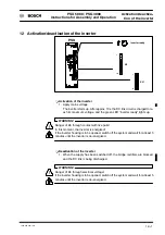
VDE 0113 is to be provided (e.g. by earthing the welding gun)! In addition, the
transformer is to be marked accordingly (see also dimensioned drawing of the
transformer, Section 10.2).
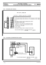
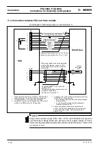
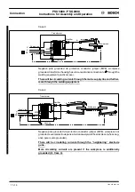
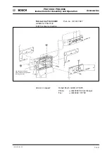
PSU 5200
green
yellow
PSG 3100
white
brown
3 thermostatic
switches connected
in series
white
brown
yellow
current sensor
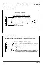
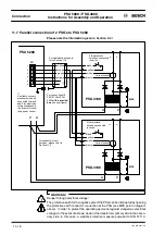
PSG 3100
3 thermostatic
switches connected
in series
white
brown
yellow
current sensor
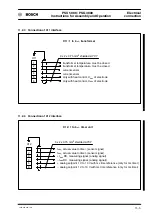
for cable data, please refer
to Section 11.5
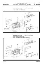
Connection of two PSG 3100 to
PSU 5200 with a terminal box
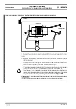
Terminal box
Connecting cable:
2 x 2 x 0.75 mm
2
shielded LiYCY
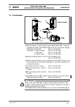
For part no., see section 14.
Brush leads approx. 150 mm
long. The connector makes, if
any, are customer--specific and
are available as accessories.
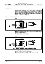
Connecting cable:
2 x 2 x 0.75 mm
2
shielded LiYCY
For part no., see
section 14.
Brush leads approx. 150 mm long.
The connector makes, if any, are
customer--specific and are available
as accessories.
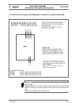
black
black
1
3
X11
2
4
5
6
Summary of Contents for PSG 3000 Series
Page 1: ...PSU 5000 PSG 3000 Instructions for Assembly and Operation MF Welding Inverters 109 Version ...
Page 3: ......
Page 5: ...PSU 5000 PSG 3000 Instructions for Assembly and Operation 1070 078 224 109 ...
Page 97: ...PSU 5000 PSG 3000 Connection Instructions for Assembly and Operation 1070 078 224 109 11 18 ...
Page 101: ...PSU 5000 PSG 3000 Maintenance Instructions for Assembly and Operation 1070 078 224 108 13 2 ...
Page 105: ...PSU 5000 PSG 3000 Instructions for Assembly and Operation Accessories 1070 078 224 108 14 4 ...
Page 113: ...PSU 5000 PSG 3000 Instructions for Assembly and Operation Index 1070 078 224 109 17 4 ...
Page 114: ...1070 078 224 109 98 10 GB MBA AT VWS Printed in Germany ...


