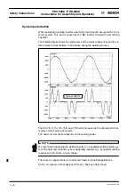
PSU 5000 / PSG 3000
Functional
description
Instructions for Assembly and Operation
1070 078 224--- 108
3--4
3.3 Faults
In order to ensure a high operational reliability, various monitoring functions are in-
corporated in the PSU module. Any occurring fault is signalled at a seven--segment
display of the PSU. The fault number may also be transmitted as a binary code to a
PLC.
The Bosch weld timer signals ”Power supply fault” (Temperature monitoring circuit
of power supply unit).
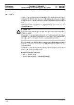
ATTENTION!
Danger of injury and of damage to property through missing or false interpretation
of fault messages!
If the inverter is not controlled by a Bosch timer, it must be ensured that closing of
the floating contact between terminals 4 and 5 or opening of the contact between
terminals 5 and 10 of connector X5 on the inverter will stop the timer!
When the cause of the fault has been eliminated, the fault message must first be
reset with the reset key or via the reset input of the PSU and then with the reset key
on the weld timer.
For the individual monitoring functions and diagnostics messages, please refer to
Section 7, ”Monitoring and diagnostics”.
Monitoring displays at the PSU
-- LED ”
⇑
” (inverter ready)
-- seven--segment display ”?” (diagnostics display)
!
Summary of Contents for PSG 3000 Series
Page 1: ...PSU 5000 PSG 3000 Instructions for Assembly and Operation MF Welding Inverters 109 Version ...
Page 3: ......
Page 5: ...PSU 5000 PSG 3000 Instructions for Assembly and Operation 1070 078 224 109 ...
Page 97: ...PSU 5000 PSG 3000 Connection Instructions for Assembly and Operation 1070 078 224 109 11 18 ...
Page 101: ...PSU 5000 PSG 3000 Maintenance Instructions for Assembly and Operation 1070 078 224 108 13 2 ...
Page 105: ...PSU 5000 PSG 3000 Instructions for Assembly and Operation Accessories 1070 078 224 108 14 4 ...
Page 113: ...PSU 5000 PSG 3000 Instructions for Assembly and Operation Index 1070 078 224 109 17 4 ...
Page 114: ...1070 078 224 109 98 10 GB MBA AT VWS Printed in Germany ...

