


PSU 5000 / PSG 3000
Instructions for Assembly and Operation
Monitoring and
diagnostics
1070 078 224--- 108
7---5
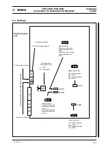
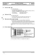
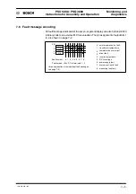
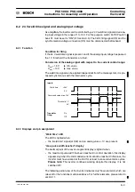
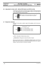
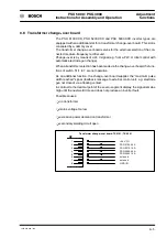
7.6 Fault message encoding
All fault messages indicated at the seven--segment display can also be transmitted
in binary code to an external PLC for evaluation. The pin assignment of output bits 1
to 4 is shown on page 7--2.
O1
O2
O3
O4
Fault number:
1
Points mean: +24 V DC at terminals 1 -- 4
2 3 4 5 6 7 8
0
power supply fault
driver fault
overcurrent / earth fault
inverter temperature
DC link voltage
transformer temperature
thermal diode overcurrent
measuring loop fault
normal operation; no fault
1
2
3
4
5
6
7
8
0
(for an explanation of the individual fault messages,
see page 7--3)
1
2
3
4
X21
Summary of Contents for PSG 3000 Series
Page 1: ...PSU 5000 PSG 3000 Instructions for Assembly and Operation MF Welding Inverters 109 Version ...
Page 3: ......
Page 5: ...PSU 5000 PSG 3000 Instructions for Assembly and Operation 1070 078 224 109 ...
Page 97: ...PSU 5000 PSG 3000 Connection Instructions for Assembly and Operation 1070 078 224 109 11 18 ...
Page 101: ...PSU 5000 PSG 3000 Maintenance Instructions for Assembly and Operation 1070 078 224 108 13 2 ...
Page 105: ...PSU 5000 PSG 3000 Instructions for Assembly and Operation Accessories 1070 078 224 108 14 4 ...
Page 113: ...PSU 5000 PSG 3000 Instructions for Assembly and Operation Index 1070 078 224 109 17 4 ...
Page 114: ...1070 078 224 109 98 10 GB MBA AT VWS Printed in Germany ...


