background image

Easy Series

Overview | en

11

Bosch Security Systems, Inc.

System Reference Guide

F01U087835 | 02 | 2008.10

1.3.2

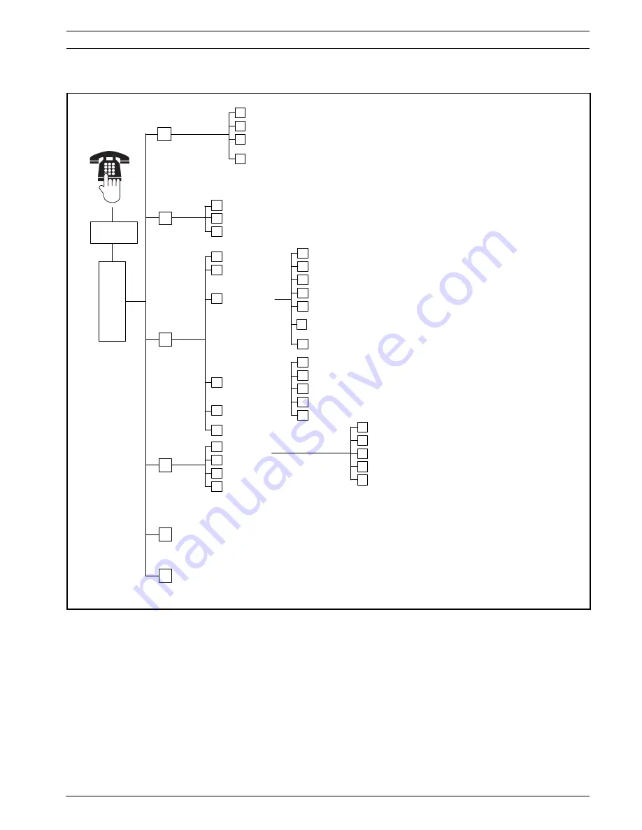
User Phone Menu

Exit system test menu

Two-Way
Voice Session

Talk to person at control center

Listen to person at control center

End voice session

1

2

#


Exit 

1

2

#

Event history

System test menu

1

Set date and time

Full system test

Reset system

2

3

Warning device test

Battery test

Communication test

Control center test

Point test

1

2

3

4

5

#

4

5

Exit

#

Most recent events

Events by date

Last alarm event

Last 10 events

Exit

1

2

3

4

#

System 
Maintenance

2

3

Phone 

Menu

Enter user 

passcode

1

To hear this option, custom protection must be 
enabled.

Only use this option 
on non-UL systems.

Turn System On or Off

5

To turn an output on or off, press the 
corresponding number key on the phone.

Operate Outputs

Turn system on and leave

Turn system on and stay inside

Turn on custom protection

1

2

3

#

Exit

End phone session.

}

The voice session only lasts 90 seconds.
To reset the timer, press [1] on the phone during talk mode, 
or [2] during listen mode.

User Menu

3

Add new user

Change user

Delete user

1

2

3

4

#

Exit

To add or change a user:

}

Operate outputs

OR

Expert Programming (Enable Installer Access)

4

6

Only the Master User can 
access the full User Menu. 
Users 2 to 21 can only change 
their own passcode.

Change token

Record description

Change passcode

Change key fob

Exit

1

2

3

4

#


1

 Only a user passcode (Users 1 to 21) can access the User Menu.


2

 If the system is on, the System Maintenance option is not available.

3

 Only the master user can add, change, or delete users. Users 2 to 21 can only change their own passcodes. User voice descriptions are 

stored in the voice module and are not transferred to the control panel with programming data.


4

 Option 6 allows the master user (User 1) to enable the Installer Passcode. Refer to Expert Programming Item Number 142 in 

Section 5.2.2 System Programming Items

, Page 43.

Availability of the menu items shown above depends on the system's status.

When recording any description (point, output, user, or custom message), do not press any buttons on your phone until prompted 

by the system.

Summary of Contents for ICP-EZM2

Page 1: ...Easy Series ICP EZM2 en System Reference Guide ...

Page 2: ......

Page 3: ...Prepare the wLSN Hub for Site Testing and RFSS Mode 19 2 5 2 wLSN Installation Tool Mode 1 19 2 5 3 wLSN Installation Tool Mode 2 20 2 5 4 wLSN Installation Tool Mode 3 21 2 6 Install wLSN Devices 22 2 7 Configure the System from the Installer Phone Menu 22 2 7 1 Upgrade the Control Panel Optional 22 2 7 2 Initiate a Phone Session from the Control Panel 22 2 7 3 Configure Required Control Panel Se...

Page 4: ...e Reporting Options 50 5 2 6 Point Programming Items 52 5 2 7 Output Programming Items 54 5 2 8 Control Center Programming Items 55 5 2 9 User Programming Items 56 5 2 10 Factory Default 57 5 3 Exit Programming 57 6 Control Panel Event Codes SIA and Contact ID 58 7 Default the System 60 7 1 Default the Control Panel and the wLSN Hub 60 7 2 Default wLSN Devices 60 8 System Test and Maintenance 61 8...

Page 5: ...etectors 82 10 9 wLSN Door Window Contact 83 10 10 wLSN Recessed Door Window Contact 83 10 11 wLSN Mini Door Window Contact 84 10 12 wLSN Inertia Detector 85 10 13 wLSN Key Fob 87 10 14 wLSN Relay Module 89 10 15 wLSN Indoor Siren 90 10 16 wLSN Outdoor Siren 91 10 17 wLSN Smoke and Heat Detectors 92 10 18 wLSN Glassbreak Detector 95 10 19 wLSN Water Sensor Low temperature Sensor 100 11 Programming...

Page 6: ...tallation Workflow 1 2 System Components and Wiring Refer to Figure 1 1 through Figure 1 3 for overviews of the system components and wiring Figure 1 1 System Component Wiring Overview Step Description Page 1 Plan the Installation Identify suitable locations for system component in the installation site Page 12 2 Install the Hardware Install all system components Page 13 3 Perform RFSS Site Test P...

Page 7: ...ff 5 ITS DX4020 G Data Bus Adr 134 Fixed 6 Supervised Points single EOL Normally open and normally closed options 2 2k Ω 7 Supervised Points dual EOL Normally closed 2 2k Ω 8 Keyswitch Options single and dual EOL 2 2k Ω 9 Prog Output PO 1 Options Switched 12v Switched Ground Dry Contact 10 Prog Outputs 2 4 NF A2P requires that sirens have a backup battery When this siren requires a 14 1V to 14 4V ...

Page 8: ...087835 02 2008 10 System Reference Guide Bosch Security Systems Inc Figure 1 2 Overview of the System Component Location for the ICP EZM2 R Enclosure Figure 1 3 Overview of the System Component Location for the ICP EZM2 EU Enclosure ...

Page 9: ...und connection Connect ground wire from enclosure to enclosure door 4 Module mounting location ITS DX4020 G shown 5 Module mounting location DX2010 shown 6 System test button When the system is completely installed and programmed press the system test button to start a full system test 7 Port for ICP EZVM voice module 8 Enclosure terminal cover ICP EZM2 R Enclosure only Shipped in hardware bag Ins...

Page 10: ...user menu 2 1 Installer Passcode 3 Points Report configuration 2 1 Record point description Set point type Exit 2 1 Enter account number Configure report destinations Remote programming success Exit 2 3 1 Exit Outputs Country code 3 4 Select output function Exit 1 Expert Programming 4 Enter programming item enter selection Two Way Voice Session 5 Talk to person at control center Listen to person a...

Page 11: ...ds To reset the timer press 1 on the phone during talk mode or 2 during listen mode User Menu 3 Add new user Change user Delete user 1 2 3 4 Exit To add or change a user Operate outputs OR Expert Programming Enable Installer Access 4 6 Only the Master User can access the full User Menu Users 2 to 21 can only change their own passcode Change token Record description Change passcode Change key fob E...

Page 12: ... into the building installation wiring 2 Test for GSM signal strength Use your cell phone to identify an area with good GSM signal strength by monitoring the signal strength on your mobile phone If the intended location of the control panel has poor GSM signal strength find a new location for the control panel 3 Identify the location for the control center Plan to install the control center near t...

Page 13: ...l Enclosure 1 Remove the desired knockouts from the control panel enclosure and optional mounting skirt 2 Attach the optional mounting skirt to the enclosure 3 Route the wires through the desired knockouts 4 Mount the enclosure to the desired surface Use proper anchor and screw sets when you install the enclosure on non load bearing surfaces such as drywall i NOTICE Use proper anchor and screw set...

Page 14: ...erminals to the control panel data bus terminals Refer to Figure 1 1 Page 6 5 Connect the control center audio bus terminals to the control panel audio bus terminals Twisted pair wiring is recommended for audio bus terminals Refer to Figure 1 1 Page 6 6 Reconnect the control center and base and then lock the control center Refer to Section Control Center Display States Page 75 for an overview of t...

Page 15: ...he orientation shown in Figure 9 1 Page 62 and then Insert the SIM card into the cardholder door the notched edge is away from the hinge d Close the cardholder door and then slide the door downward to lock it 2 Mount the communicator into the control panel s enclosure using the side wall mounting location 3 Place the magnetic antenna on the panel enclosure on top recommended for vertical polarizat...

Page 16: ...ions P N F01U045288 for more information 1 Set the DX4020 s DIP switches to Address 134 for network communication 2 Mount the DX4020 into the control panel s enclosure using the back wall or side wall mounting location 3 Connect the DX4020 to the control panel Refer to Figure 1 1 Page 6 2 2 8 Connect Supervised Points For wiring diagrams refer to Figure 1 1 Page 6 Fire Point Wiring Supervised Poin...

Page 17: ...Figure 2 3 Page 17 Figure 2 3 Cable tie for MAINS to Power Supply 3 Place the terminal cover over the power supply terminals i NOTICE Because the control panel is permanently connected equipment a readily accessible disconnect device must be included into the building installation wiring An external earth ground is required to ensure safe and proper system operation Failure to ground the system ca...

Page 18: ... sec Intermittent flashing green icon LED on steady 2 15 45 sec Flashing amber circle 3 45 75 sec Single rotating amber segment 4 75 sec Solid green circle i NOTICE Before permanently installing any wLSN device verify that the radio frequency signal strength RFSS between the planned device location and the planned wLSN Hub location is acceptable CAUTION If you have wireless devices that you will n...

Page 19: ...es if a device location has acceptable or unacceptable RFSS To test the wireless devices with the Installation Tool in Mode 1 1 Verify that the wLSN Hub rotary switch is set to S1 9 S2 2 S3 0 Refer to Figure 1 1 Page 6 The wLSN Hub s LED flashes slowly 2 Go to the first device location and then press and hold on the Installation Tool for 2 sec 3 Press 1 for Mode 1 4 Place the Installation Tool in ...

Page 20: ...ght position at the first device location or hold it in the location if necessary 5 Wait 10 sec and then review the display The Mode 2 display shows power bars on the left and the number of packets received on the right The bars indicate the signal strength The Installation Tool shows the number of packets received 1 2 or 3 Table 2 4 Mode 2 Display Data If the location tests OK Confirm that the lo...

Page 21: ...llation Tool in an upright position at the first device location or hold it in the location if necessary 5 Wait 10 sec and then review the display In the Mode 3 display SNR yy refers to the signal to noise ratio in dB and x is the RFSS value in dBm The Mode 3 display shows the signal to noise ratio SNR at the test spot S refers to the signal strength of the incoming message from the wLSN Hub to th...

Page 22: ...nel flashes Remove the green upgrade programming key 2 7 2 Initiate a Phone Session from the Control Panel 1 Connect a phone set to the test posts or to the phone terminals Refer to Figure 1 1 Page 6 2 Press and hold the System Test button for approximately 15 sec Figure 1 2 Page 8 for the location of the Test button 3 When prompted use the phone set to enter the installer passcode default is 5432...

Page 23: ...der that the devices first communicate to the system tampered faulted low battery If specific point numbers are preferred for wireless devices ensure that the wireless devices communicate in the appropriate order Otherwise the system assigns the lowest available point number to the first tested wireless device With motion detectors unmask only the detector you want to test Device To Test Motion De...

Page 24: ...to enter the User Menu 2 From the User Phone Menu press 4 to enter the User Menu 3 Press 1 to add a new user After you add a new user you can also assign a token passcode and key fobs to that user 4 Repeat Step 4 to add more users 5 Press to return to the User Menu Water Sensor Low temperature Sensor Water Sensor Select one of the following methods Short the water probe pins for at least 5 sec Sub...

Page 25: ... CMS and control panel polling rate 3 Observe the BUS LED The LED stays on steady when the communicator has permission to be configured Refer to Figure 9 1 Page 62 for LED locations Refer to row 2 in Table 2 9 Page 26 4 Observe the SS1 LED to confirm the ITS DX4020 G is registered and has sufficient signal strength to configure it by SMS The SS1 LED must be On to continue Refer to Figure 9 1 Page ...

Page 26: ...or Configuration mode or authorization is not required GSM Signal Strength On 3 Received invalid SMS Flash Flash Flash Flash 4 Received valid SMS authorizing configuration Key Scrolling LEDs from left to right LED s status does not matter Shifting flash Every other LED flashes simultaneously creating the shifting flash pattern i NOTICE If the LEDs indicate an invalid SMS remove the configuration j...

Page 27: ... using Programming Item Number 362 refer to Section System Report and Restoral Routing page 51 Then send a test report using the PTSN using GSM destination and observe the LEDs Refer to Section 2 8 3 Test ITS DX4020 G Communications page 27 for configuration information To use the Manual Communicator Test a Set the Format for Route 2 Primary Destination Programming Item Number 213 the same as the ...

Page 28: ...ocation 4 Determine if the RF signal strength is acceptable by observing the device s LED flash pattern The flash pattern appears for 10 min Refer to Table 3 1 Page 28 Table 3 1 wLSN Device LED Flash Patterns in RFSS Mode 3 2 Establishing the Wireless Network and Configuring Wireless Devices In order for the wireless network to operate properly the following process must occur as shown below LED F...

Page 29: ...tem Test OR Press 1 and then press 3 to select System Test Menu From the System Test Menu press 5 to select Point Test Wireless Configuration Menu 1 Enter the Installer Menu of a phone session refer to Section 2 7 2 Initiate a Phone Session from the Control Panel Page 22 2 Press 1 6 to select System Maintenance Wireless Configuration The device discovery process automatically starts 3 2 2 Establis...

Page 30: ...phone session or press and hold 3 on the control center and enter the master user User 1 passcode 3 Press 4 1 4 Enter a passcode and then re enter the passcode 5 Press 4 to add a key fob Token assignment and voice description are optional 6 Repeat Steps 4 to 7 to add more users and key fobs or press repeatedly to end the phone session To create a key fob only system no wireless input or output dev...

Page 31: ...e The new device replaces the current device If other devices were discovered in Step 2 they are returned to the undiscovered state 2 Add a Device Use this option to add more devices to the wireless network When you press 2 to select this option the device discovery process starts When the system announces Test all points activate all of the new devices If other devices were discovered but not act...

Page 32: ...ch the wireless data in the hub Bus Device Trouble 50 use this option to erase the wireless data in both the control panel and hub and rediscover all devices This option is only available if the wireless data does not match in the control panel and hub Exit Wireless Configuration Select this option to return to the System Maintenance options Button Press Menu Option Description System Message Desc...

Page 33: ... the Phone Menus you can copy the programming from the control panel to a programming key for use on another control panel or for backup Refer to Section 4 3 Programming Keys page 36 Options Steps House Phone Press Listen for the voice prompt to enter a passcode Enter the installer passcode to access the installer menu or a user passcode to access the user menu Outside Phones Call the premises pho...

Page 34: ...his option is the primary method to use for establishing a connection between RPS and the control panel Connect the internal modem on the RPS PC or an external modem to the control panel Manual Dial 1 Either the installer or RPS operator establishes a phone connection between the control panel and RPS The installer dials the RPS phone number using the house phone or connects a test telephone to th...

Page 35: ...the DTMF tone to connect to the control panel Direct Connect Select this method to establish a local on site connection between the RPS PC or laptop and the control panel 1 On the Telco side of the phone line ensure that Tip and Ring are disconnected 2 Connect the internal modem on the RPS PC or an external modem to the control panel Refer to Figure 4 1 Page 35 Figure 4 1 Modem Connections 3 If th...

Page 36: ...y Lock Positions 3 Insert the key into the control panel board Auto Transfer If Expert Programming Item Number 123 1 refer to Programming Key Auto Transfer in Section 5 2 2 System Programming Items page 43 the programming key automatically transfers data depending on the position of the lock switch Manual Transfer If Expert Programming Item Number 123 0 you must use the Installer Menu to access th...

Page 37: ... configuration Only use expert programming if you have a special programming requirement i NOTICE You can program control panels using the remote programming software RPS Like Expert Programming RPS allows access to all programming categories For more information on RPS and how to use a programming key to streamline a multiple panel install refer to Section 4 Programming Access Options page 33 i N...

Page 38: ...amming Refer to the figure below for the Basic Programming Menu options Installer Phone Menu Programming Key Custom Messages Two Way Voice Session Expert Programming Basic Programming User Menu System Maintenance Points Report Configuration Outputs Country Code Exit basic programming 1 2 3 4 Record point description Set point type Exit points 1 2 Enter account number Configure report destinations ...

Page 39: ...ted Press 1 to continue programming the selected point Press 2 to re record your current point description 2 Set Point Type Refer to Point Type table Press 1 to select the current option Press 2 to hear more options Press to exit Point Type Point Types Disabled Perimeter Entry or Exit Interior Follower Perimeter Instant 24 Hour Fire Verified Fire Verified Fire Instant Point Types cont Silent Panic...

Page 40: ...UTE 1 ROUTE 2 Phone Number Enter phone number to dial and follow prompts IP Address Enter as first character then follow prompts 2 Route 1 Backup 3 Route 2 Primary 4 Route 2 Backup Phone Number or IP Address Phone Number or IP Address Phone Number or IP Address Account Number Entries Phone Number IP Address Entries Entry Key Press Entry Key Press 0 to 9 0 to 9 0 to 9 0 to 9 B 1 C 2 D 3 1 E 4 Pause...

Page 41: ...or Intrusion and Fire System On Unoccupied Exit Points Return to Installer Menu i NOTICE When the installer PIN is entered at the keypad or phone a 3 sec time window starts During that time window a tamper alarm activates the interior siren for only 1 sec Open the enclosure door during this time to silence the sirens during maintenance Once the enclosure is closed tamper alarm is restored after a ...

Page 42: ...ng your phone s keypad For example press 1 to enable phone line supervision 3 Repeat Steps 1 and 2 to configure other programming items or press to exit Expert Programming The following sections list programming items item numbers possible selections and default values Record custom values in the Entry column next to the respective default value Installer Phone Menu Programming Key Custom Messages...

Page 43: ...Enclosure Tamper Enabled 103 0 Disabled 1 Enabled 1 Fire Bell Cut Off Time 107 0 to 90 min 5 Intrusion Bell Cut off Time 108 0 to 90 min 5 Intrusion Abort Window 110 15 to 45 sec 30 Fire Alarm Cancel Window 111 0 to 10 min 0 Intrusion Cancel Window 112 5 to 10 min 5 Chime Tone Select 114 1 Chime door bell 2 Single chime 3 Standard door bell 1 Chime Mode Operation After System Off 115 0 Off 1 On 2 ...

Page 44: ...der Options 133 1 Stay Leave Custom 2 Stay Custom Leave 3 Leave Stay Custom 4 Leave Custom Stay 5 Custom Leave Stay 6 Custom Stay Leave 1 Cross Zone Timer 134 60 to 3600 sec 120 Clear Alarm Memory 136 0 By user 1 By master user 0 Latching Point and Enclosure Tamper 137 0 Any user can clear condition 1 Only the installer can clear condition 0 Latching System Device Tamper 138 0 Any user can clear c...

Page 45: ...ing Item Number 125 0 Two Way Voice Session Configuration 158 0 Allow at any time 1 Allow only during alarm conditions 0 Start Arming with Faulted Points 159 0 Force arm all faulted points 1 Exit Delay starts with faulted points 1 Speak Active Faults 160 0 Call for Service announced 1 Fault condition announced 0 Wireless Transmission Attenuation 161 Temporary attenuation for installation and maint...

Page 46: ...Duress event enabled 0 Key Fob Button Configuration 616 0 Status request only 1 Turn system on occupied 2 Turn system on custom protection 3 Turn output on or off 4 Turn output on for 2 sec 0 Key Fob Button Configuration 626 0 Default Country specific default Select this programming item to hear the updated default value or refer to Section 11 3 Country Code Specific Default Programming Codes page...

Page 47: ...tempts 204 1 to 5 in increments of 5 sec 1 Dial Tone Detect 205 0 Do not wait for dial tone 1 Wait for dial tone 1 Route 1 Primary Destination 206 Enter a phone number up to 32 digits or IP address 000 000 000 000 to 255 255 255 255 for each destination 0 to 9 0 to 9 Pause 1 Exit with save Exit without save Press twice within two seconds to exit without saving your entry Disable phone number 0 Dis...

Page 48: ... for Route Destination Route 1 Primary 241 Route 1 Backup 242 Route 2 Primary 243 Route 2 Backup 244 241 0 to 65535 7700 242 7700 243 7700 244 7700 Heartbeat for Route Destination Route 1 Primary 281 Route 1 Backup 282 Route 2 Primary 283 Route 2 Backup 284 281 0 Disabled 1 to 65535 min 0 282 0 283 0 284 0 Acknowledge Wait Time for Route Destination Route 1 Primary 285 Route 1 Backup 286 Route 2 P...

Page 49: ...ll in Time Minutes 226 0 to 59 RPS Automatic Call in Time Day of Week 227 0 to 6 where 0 Sunday and 6 Saturday RPS Automatic Call in Time Day of Month 228 1 to 28 RPS Automatic Call in Phone Number 229 Enter a phone number up to 32 digits or IP address 000 000 000 000 to 255 255 255 255 for each destination 0 to 9 0 to 9 Pause 1 Exit with save Exit without save Press twice within two seconds to ex...

Page 50: ...ouble 324 3 Cross Zone Trouble 393 3 Intrusion Trouble Restoral 325 3 Alarm Recent Close 394 3 Intrusion Zone Bypass 326 3 Panic Restoral 399 3 Intrusion Zone Bypass Restoral 327 3 Cross Zone Trouble Restoral 400 3 Enter a value to globally set all of the following reports to the same value To modify one a specific report enter a value in that report s item number 0 Neither route 1 Route 1 only Pr...

Page 51: ... 351 3 3 Local Programming Success 357 3 Bus Device Trouble 373 3 Low Battery 358 3 Bus Device Trouble Restoral 374 3 Low Battery Restoral 359 3 ROM Fault 375 3 Communication Test Manual 362 3 Bell Trouble 376 3 Phone Line Fault 363 3 Bell Restoral 377 3 Phone Line Fault Restoral 364 3 Walk Test End 378 3 Remote Programming Failure 365 3 Walk Test Start 379 3 Remote Programming Success 366 3 Bus D...

Page 52: ... 9021 9031 9041 9101 9151 9201 9321 Point Type 0 Disabled 1 Perimeter 2 Interior 3 Perimeter Instant 4 24 Hour 5 Fire Verified 6 Fire Instant 7 Silent Panic 8 Interior Walkthrough 9 Perimeter Exit Cancel 11 Momentary Keyswitch 12 Maintained Keyswitch 13 24 Hour Trouble 14 User Emergency 9012 9022 9032 9042 9102 9152 9202 9322 Circuit Style 0 Dual 2 2 kΩ alarm and tamper circuit 2 Single 2 2 kΩ ala...

Page 53: ...high sensitivity Inertia Detector Minor Attack Options 8 Tap on 8 taps low sensitivity 9 Tap on 8 taps low medium sensitivity 10 Tap on 8 taps medium high sensitivity 11 Tap on 8 taps high sensitivity 12 Tap on 4 taps low sensitivity 13 Tap on 4 taps low medium sensitivity 14 Tap on 4 taps medium high sensitivity 15 Tap on 4 taps high sensitivity Programming Item Number bold digits Point Number Pr...

Page 54: ... 15 System On Unoccupied 16 Intrusion and Fire 2 5 Output 2 Function wired 621 5 Output 3 Function wired 631 5 Output 4 Function wired 641 7 Output 5 Function wireless 651 5 Output 6 Function wireless 661 0 Output 7 Function wireless 671 0 Output 8 Function wireless 681 0 Output 4 Supervised Speaker Driver wired 642 0 Supervised 8 Ω speaker driver 1 Unsupervised open collector 0 Default Country sp...

Page 55: ...buttons are enabled Programming Item Item Number Selections Manuf Default Alarm Message Minimum Repeat Time 880 1 to 255 hrs 12 No Alarm Report Sent Announcement 883 0 Announcement disabled 1 Announcement enabled 1 Cancel Report Sent Announcement 884 1 Time Format 887 0 Determined by voice module 1 Always use 12 hr mode 2 Always use 24 hr mode 0 Programming Item Item Number Selections Manuf Defaul...

Page 56: ...untry specific default Select this programming item to hear the updated default value or refer to Section 11 3 Country Code Specific Default Programming Codes page 108 Programming Item Item Number Selections Manuf Default Passcode Length 861 Set the length of all passcodes 4 or 6 digits 4 Installer Passcode User 0 7001 Four digit Range 1111 to 5555 Six digit Range 111111 to 555555 5432 543211 Mast...

Page 57: ...er Selections Factory Default 9999 Enter 9999 to restore all factory default values All programming items except for the country code are reset when you restore the factory default values This item also deletes all wireless data but does not default the wireless hub WARNING For NF A2P installations once the panel is configured check that all parameters are within the range of authorized values Ref...

Page 58: ...osing 1 459 Recent Closing Close System On Unoccupied CL Closing Report 3 401 Unoccupied Arm by User Close System On Occupied CL Closing Report 3 441 Occupied Arm by User Close System On Custom CL Closing Report 3 441 Custom Arm by User Close System On Partial CL Closing Report 3 456 Partial Arm by User Close System On Keyswitch CS Closing Keyswitch User 255 3 409 Keyswitch O C User 255 Open Syste...

Page 59: ...eless Point Low Battery XT Transmitter Battery Trouble 1 384 RF Low Battery Wireless Point Low Battery Restoral XR Transmitter Battery Restoral 3 384 RF Low Battery Wireless Receiver Jammed XQ RF Interference 1 344 RF Receiver Jam Detect Wireless Receiver Jammed Restoral XH RF Interference Restoral 3 344 RF Receiver Jam Detect Bus Device Tamper XS RF Receiver Tamper 1 341 Exp Module Tamper Bus Dev...

Page 60: ... the base yet 9 Reapply all power to the system 10 Default the control panel from the Installer Menu of a phone session Section 2 7 2 Initiate a Phone Session from the Control Panel Page 22 press 4 to select Expert Programming 11 Press 9 9 9 9 to restore all factory default values 12 Remove all power to the system 13 Reconnect the wLSN Hub to the base 14 Reapply all power to the system 15 Default ...

Page 61: ...umber indicates the route 1 event status The second number indicates the route 2 event status The numbers in each announcement indicate the status as follows 0 The event was logged only 1 The event was successfully transmitted for this route 2 The transmission of this event failed for this route 3 The event is still pending for this route Refer to the following table for a history event announceme...

Page 62: ...e SMS Terminal Interface on a PC connected using a USB port Figure 9 1 ITS DX4020 G Communicator 1 Mini USB Port 8 Signal Strength 1 SS1 LED 2 Antenna Connector 9 Signal strength 2 SS2 LED 3 CONFIG MODE J200 Jumper Pins 10 Signal strength 2 SS2 LED 4 LED DIS J201 Jumper Pins 11 Bus LED 5 STATUS LED 12 SIM Cardholder 6 CELL IP LED 13 SIM Card In Cardholder Door Open 7 AUDIO ACT LED i NOTICE To cons...

Page 63: ... Page 69 and Table 9 7 Page 69 for descriptions of each parameter ID in the SMS format Table 9 1 ITS DX4020 G SMS Format The configuration SMS string consists of a maximum of three SMS messages When the ITS DX4020 G receives the final valid part of an SMS message it accepts the configuration The communicator waits as long as the CONFIG jumper is on When the CONFIG jumper is removed all incomplete ...

Page 64: ...0203040506070809010111213141516 LF Sample AES key 14 134 LF Option bus address End of configuration 1 1 4020G 2 secret123 3 123456 4343 10 basic m2m 11 user telco com 12 password 15 1 16 010203040506070809010111213141516 14 134 SMS Line No Description Sample SMS 1 LF SMS sequence number 1 4020G LF Current password 2 secret123 LF New password case sensitive 3 123456 4343 LF PUK and new PIN to set i...

Page 65: ...Systems 5 Under Intrusion Alarm Systems click Conettix Information Transport Solutions 6 To the right of ITS DX4020 G INF click EN The File Download window opens Figure 9 2 File Download Window 7 Click Save to save the file to the target PC or laptop 9 3 2 Installing the ITS DX4020 G USB Driver If the target PC or laptop only has one USB port you only need to install the USB driver once If the tar...

Page 66: ...Options Window 4 Under Search for the best driver in these locations click the Include this location in the search option and then click Browse The Browse for Folder window opens Figure 9 5 Browse For Folder Window 5 In the file directory go to the location where you saved the ITS DX4020 G inf file Click OK and then click Next The Found New Hardware Finish window opens Figure 9 6 Found New Hardwar...

Page 67: ...w control None 2 Press Enter The ITS DX4020 G USB login screen opens Figure 9 7 ITS DX4020 G USB Login Screen 3 Enter a valid password to log on The default password is 4020G all uppercase The user interface allows three attempts to correctly enter the password After three failed attempts you must reset the ITS DX4020 G by removing the jumper plug from the CONFIG jumpers 4 Press Enter to continue ...

Page 68: ...er the new password twice The second entry is to confirm the new password Passwords must be 4 15 characters long and they are case sensitive 0 9 A Z a z and special characters are allowed 2 Change log level 2 Change the debugging level shown on the View Log screen 3 View log 3 View the debugging log Press any key to exit 4 Exit without Save 4 Return to the user interface login screen All configura...

Page 69: ... ITS DX4020 G 14 Bus Address 134 SDI 80 88 Option Bus 134 Sets the option bus address for communication with the control panel For Easy Series use Address 134 15 AES Encryption 0 0 Disabled 1 Enabled Security encryption on off must match encryption settings in the receiver 16 AES Encryption Key blank 32 characters max 0 9 A F a f allowed Key must match encryption key in the receiver ID Parameter D...

Page 70: ...5 Under Intrusion Alarm Systems click Conettix Information Transport Solutions 6 To the right of ITS DX4020 G_x x x bin click EN The File Download window opens 7 Click Save to save the file to the target PC or laptop 9 4 2 Installing the Software with Hyper Terminal Microsoft includes Hyper Terminal with the Windows XP operating system and earlier operating systems 1 In Windows click Start All Pro...

Page 71: ...erm on the target PC or laptop 1 Start Tera Term 2 Select File Transfer XMODEM Send Figure 9 10 Tera Term File Menu Path 3 In the XMODEM Send window use the Look in menu to find the location where you downloaded the ITS DX4020 G binary file 4 Click Open to start the software upgrade Figure 9 11 Tera Term XMODEM Send Window 5 When the software upgrade is complete close Tera Term and remove the jump...

Page 72: ... All points support four wire smoke detectors Enclosure tamper input does not reduce point capacity Reaction time lower than 250ms Programmable Outputs PO On board 4 PO 1 only Configurable relay PO 2 to PO 4 Configurable solid state PO 4 only Internal supervised speaker driver option PO 1 Relay Rating Contacts 2 A with no jumper installed resistive loads only in a NF A2P certified installation 1 A...

Page 73: ...nal 11 2 VDC to 12 3 VDC The control panel stops processing point faults when the voltage drops below 9 5 VDC Battery D126 7 Ah or D1218 18 Ah sealed lead acid rechargeable 1 7 A maximum recharging current Low battery condition occurs when battery drops below 12 VDC If AC power fails and the battery drops below 9 5 VDC the control panel stops processing point faults Disconnect the battery under th...

Page 74: ... supply A AC Power On Normal Current B AC Power Off Minimum Current C In Alarm Maximum Current Model Qty Used Each Unit mA Total mA Each Unit mA Total mA Each Unit mA Total mA Control Panel 85 x1 85 85 x1 85 160 x1 160 Control Center 110 x Qty 110 xQty 165 xQty Wireless Hub IWT WSN N 86 30 x Qty 30 x Qty 30 xQty DX2010 35 x Qty 35 x Qty 0 35 xQty Sounders Connected to PO 4 D118 8 Ω Speaker 0 xQty ...

Page 75: ... conductor power limited 1 2 mm 18 AWG or 0 8 mm 22 AWG wire Only two conductors are used At least 0 6 mm 24 AWG twisted pair CAT5 wire UL installations require power limited wiring Unless using CAT5 cable audio bus connections require a dedicated wire CAT5 Wire Requirements Refer to Section 2 2 3 Install the Control Center page 14 Protection Level IP 30 IK 04 Display Color Description Green circl...

Page 76: ...Display Color Description Display Color Description Flashing red icon Exit Delay in progress Circle segments turn on one at a time to provide a visual status of Exit Delay Red System is on occupied or custom protection Flashing icon amber then red Entry Delay in progress Circle segments turn off one at a time to provide a visual status of Entry Delay Amber icon First half of Entry Delay Red icon S...

Page 77: ...ogress Red System is on unoccupied Flashing icon amber then red Entry Delay in progress Amber icon First half of Entry Delay Red icon Second half of Entry Delay Broken red circle flashing red icons Fire or intrusion alarm occurred Flashing red circle Active alarm memory if system is on Single red rotating segment Alarm memory announcement if system is on Broken red circle At least one point is fau...

Page 78: ... 102 Points 9 to 16 and 103 Points 17 to 24 wireless points can only occupy Points 25 to 32 If you add three DX2010 modules wireless points can only occupy Points 1 to 8 If you add a DX2010 module using address 102 Points 9 to 16 wireless points can only occupy Points 17 to 32 i NOTICE If Points 9 to 32 contain wired and wireless points install all required DX2010 Input Expanders before adding any...

Page 79: ... point grouping is not available the control panel deletes the conflicting wireless points from the system 10 4 Conettix DX4020 Network Interface Module The Conettix DX4020 Ethernet Network Interface Module creates two way communications over Ethernet networks for compatible control panels 10 5 ITS DX4020 G Communicator The Conettix ITS DX4020 G Communicator is a multi function dual path security ...

Page 80: ...n Refer to Figure 10 1 on Page 80 and Table 10 4 on Page 80 Figure 10 1 wLSN Installation Tool Table 10 4 wLSN Installation Tool LED Status 868 MHz ISW BIT1 HAX ISW BIT1 HBX ISW BIT1 HCX 915 MHz ISW BIT1 HCX Power Docked 12 VDC nominal 6 VDC to 14 VDC Batteries 3 AAA NiMH rechargeable batteries that require an initial charge of at least 7 hours of charging Operating Life Up to 50 hours of continuo...

Page 81: ...r an overview on wLSN Hub LEDs and switch settings Table 10 5 wLSN Hub LED Displays Table 10 6 wLSN Hub Switch Settings 868 MHz ISW BHB1 WX 915 MHz ISW BHB1 WY Wire Gauge 0 14 mm to 1 5 mm Wire Length 100 m Power Voltage 12 VDC nominal 7 to 14 VDC Current Draw 60 mA maximum Compliance EN50131 1 Security Grade 2 Type C Environmental Class II Operation LED Display Self Test and Hardware Failure LED ...

Page 82: ...erformance and is the least sensitive to false alarms 2 Intermediate Sensitivity Only use this setting in non pet installations where environmental disturbances are minimal Intermediate sensitivity provides the highest level of detection performance 3 Setting the Dual Motion Detector s Microwave Range Adjustment a If the microwave coverage needs adjustment red or yellow LED does not light increase...

Page 83: ...toring doors A cover tamper switch transmits a tamper signal when the cover is removed from its base and windows An LED provides status for RFSS and Discovery Modes Specifications 868 MHz ISW BMC1 S135X 915 MHz ISW BMC1 S135Y Maximum Distance Between Sensor and Magnet 12 7 mm the magnet can be placed on either side The base is marked to indicate the magnet position Wire Gauge 0 14 mm 22 AWG to 1 5...

Page 84: ...h transmits a tamper signal when the cover is removed from its base or when the unit is pulled away from the wall An LED provides status for RFSS and Discovery Modes Specifications Tamper Switch Location Refer to Figure 10 3 on Page 84 for the location of the device s tamper switch Figure 10 3 Mini Door Window Contact Tamper Switch 1 Mounting slots for printed circuit board 2 Tamper switch 3 LED f...

Page 85: ...t up Refer to Figure 10 4 on Page 85 for arrow and for proper wire routing when reinserting the sensor element Figure 10 4 Sensor Adjustment 868 MHz ISW BIN1 S135X 915 MHz ISW BIN1 S135Y Maximum Distance Between Detector and Magnet 12 7 mm 1 2 in The magnet can be placed on either side of the detector Power Voltage 2 AA batteries 1 5 V alkaline Sensor Adjustment Adjust the position of the sensor e...

Page 86: ...The Minor Attack setting is very sensitive and can be disabled Test Mode The unit is automatically in Test mode for the first 10 minutes after power up The green LED flashes Once to indicate initialization is complete and the unit is in Test mode Twice to indicate a Minor Attack test Three times to indicate a Gross Attack test i NOTICE A single tap such as a branch in the wind lightly brushing a w...

Page 87: ...n and LED Locations 868 MHz ISW BKF1 H5X 915 MHz ISW BKF1 H5Y Power Voltage Two CR2032 lithium batteries 3 VDC Gaskets Interchangeable for multiple users different colors available EN50131 1 Security Grade 2 Environmental Class II 1 High intensity LED 2 Status LED 3 Disarm button 4 Arm button 5 Programmable buttons LED Button Function High intensity LED Suitable for use as a flashlight Press to op...

Page 88: ... this table occurs This display lasts approximately for 15 sec Red fast flash The system is in alarm or silent panic feature was used Red slow flash Exit delay in progress system occupied or unoccupied Red on steady The system is on occupied or unoccupied Green fast flash An error occurs while turning the system on The system does not turn on as expected Green slow flash The system is not ready to...

Page 89: ...se or when the unit is pulled away from the wall An LED provides status for RFSS and Discovery Modes Specifications 868 MHz ISW BRL1 WX 915 MHz ISW BRL1 WY Wire Gauge 0 14 mm to 1 5 mm Power Four AA batteries 1 5 V alkaline External Power Source optional 12 VDC nominal 6 VDC to 14 VDC Terminal Blocks DC and DC External power source 12 VDC nominal 6 VDC to 14 VDC PT and PT input Input supervised se...

Page 90: ... the unit is pulled away from the wall An LED provides status for RFSS and Discovery Modes Specifications 868 MHz ISW BSR1 WX 915 MHz ISW BSR1 WY Wire Gauge 0 14 mm to 1 5 mm Power Four AA batteries 1 5 V alkaline External Power Source optional 12 VDC nominal 6 VDC to 14 VDC DC and DC Terminal Blocks External power source 12 VDC nominal 6 VDC to 14 VDC Sounder 85 dB at 3 m EN50131 1 Security Grade...

Page 91: ...0 1600 Hz excursion of 200 Hz Sounder 90 to 105 dB at 1m EN50131 1 EN Environmental class IV outdoor Configuration Region DIP Switches Configuration OFF OFF Default Siren is limited to 90 sec Flashes every 1 5 sec from 0 90 sec of the alarm Flashes every 3 sec from 90 sec 30 min of the alarm Flash stopped after 30 min ON OFF Spain Siren is activated for 60 sec then 30 sec of silence and then activ...

Page 92: ... the unit is pulled away from the wall The optical chamber is removable for easy maintenance Specifications Battery Replacement The LED normally flashes every 8 sec Replace batteries when the LED stops flashing and the sensor chirps every 45 sec The low battery trouble chirps can be silenced for 24 hours by pushing the Test Silence Button Refer to Figure 10 7 on Page 92 for the location of the Tes...

Page 93: ... detector s sensitivity and the action to take Table 10 10 wLSN Smoke Detector Sensitivity Conditions Silence an Alarm Press the Test Silence Button refer to Figure 10 7 on Page 92 to silence the sounder during an alarm If smoke is still present after a few minutes the sounder and alarm resume LEDs Table 10 11 wLSN Smoke Detector LED Statuses i NOTICE To avoid a fire department dispatch contact th...

Page 94: ...d pull it up and away from the detector Refer to Figure 10 8 on Page 94 Figure 10 8 Remove the Detector Cap and the Chamber 4 Use compressed air or a soft bristled brush to remove dust and dirt from the smoke chamber base 5 Align the new optical chamber with the base and snap into place 6 To attach the detector cap line the cap up with the detector press the cap onto the detector and turn the cap ...

Page 95: ...N Glassbreak Detector Front Layout 868 MHz ISW BGB1 SAX 915 MHz ISW BGB1 SAY Power Voltage 2 AA batteries 1 5 V alkaline Acoustic Capabilities Glass types and thicknesses Type Thickness Plate 0 24 cm to 0 95 cm Tempered 0 32 cm to 0 95 cm Laminated 0 32 cm to 1 43 cm Wired 0 64 cm Protected only if both panes of glass are broken Minimum pane size for all types of glass 28 cm x 28 cm Range Maximum ...

Page 96: ...he protected glass on free standing posts or pillars in rooms with noisy equipment such as air compressors bells and power tools Sensitivity Settings 1 If the front housing is attached carefully open the service door Item 3 Figure 10 9 on Page 95 2 Enable the LEDs for test purposes by sliding the LED ENABLE switch Item 8 Figure 10 9 on Page 95 in the direction the arrow points above the switch An ...

Page 97: ...vent LED Item 6 Figure 10 9 on Page 95 for approximately 1 min If the green LED flashes relocate the unit or reduce the sensitivity by adjusting the sensitivity switch 7 Repeat Steps 3 through 6 until you achieve the best sensitivity level 8 After setting the sensitivity slide the LED enable switch Item 8 Figure 10 9 on Page 95 to the OFF position Testing Test the detector at least once each year ...

Page 98: ... the red Start button on top Item 2 Figure 10 9 on Page 95 The tester buzzes and the green LED on the detector flashes once per sec If the green LED does not flash move closer to the detector and repeat the procedure Testing Testing the Detector Flex and Audio Signals 1 Set the 13 332 Tester switches to the TEST and FLEX positions Items 1 and 3 Figure 10 9 on Page 95 2 Press the red Start button I...

Page 99: ...of the tester towards the detector and press the red Start button on top Item 2 Figure 10 9 on Page 95 The tester buzzes Entering RFSS Mode with the Wall Tamper Removed To enter RFSS Mode if the wall tamper tab is removed 1 Remove and reinsert the batteries 2 Press and hold the wall tamper switch Refer to Figure 10 12 on Page 99 Figure 10 12 Wall and Cover Tamper Switches 3 Quickly press and relea...

Page 100: ...re sensor first Refer to Table 10 13 Page 100 for instructions The system announces Point xx was tested 2 Test the water sensor Refer to Table 2 for instructions Testing and Enabling When Only the Water Sensor is Required During the Point Test test the water sensor Refer to Table 10 13 Page 100 for instructions The system announces Point xx was tested Testing and Enabling When Only the Low tempera...

Page 101: ...ce Specifications and Overview en 101 Bosch Security Systems Inc System Reference Guide F01U087835 02 2008 10 Figure 10 13 Enabling the Water Probe and Low Temperature Functions 1 Water sensor 2 Low temperature sensor ...

Page 102: ...how long a user has to cancel an intrusion alarm report after the system sends the report to the central station 115 Chime Mode Operation after System Off Determines Chime Mode operation after the system is turned off 116 Automatic Test Report Frequency Determines how often the control panel sends the automatic test report 118 RPS Passcode Enter the 6 digit passcode that allows access to the contr...

Page 103: ...em off If the Master User token is presented again the Installer passcode is disabled 3 From the phone interface the Master User enters the passcode then presses 3 for System Maintenance 3 for System Test menu and then 6 to enable the Installer s passcode 145 Test Report Day of Week Select the day that the control panel sends the test report 146 Test Report Day of Month Enter the day of the month ...

Page 104: ...n on for 1 sec at the end of Exit Delay If closing reports are enabled the outputs turn on for 1 sec when the control panel receives a closing report acknowledgement from the central station Select the hour when the control panel calls RPS 225 RPS Automatic Call in Time Minutes Select the minute when the control panel calls RPS 227 RPS Automatic Call in Time Day of Week Select the day of the week ...

Page 105: ...interruption to reset a latching alarm condition System On Output turns on when the system is turned on and remains on until system is turned off System Ready Output turns on when the system is ready to turn on no faulted points or system troubles exist Key Fob On Off Output turns on or off when the user presses the key fob s or key Key Fob 2 sec Pulse Output turns on for two seconds when the user...

Page 106: ...faulted and the system is on custom protection Entry Delay starts If the system is on occupied or unoccupied this point functions as an interior point Perimeter Exit Cancel If faulted and restored during Exit Delay Exit Delay stops and the system immediately turns on Momentary Keyswitch Turn the system on or off using a momentary keyswitch Maintained Keyswitch Turn the system on or off using a mai...

Page 107: ...Italy 25 Austria 03 Japan 26 Belarus 62 Lithuania 29 Belgium 04 Luxembourg 20 Bosnia 65 Malaysia 32 Brazil 05 Mexico 34 Bulgaria 06 Netherlands 35 Canada 07 New Zealand 36 China 08 Norway 38 Croatia 10 Poland 41 Czech Republic 12 Portugal 42 Denmark 13 Romania 43 Egypt 14 Russian Federation 44 Finland 16 Spain 51 France 17 Sweden 52 Germany 18 Taiwan 54 Greece 19 Thailand 55 Hong Kong 20 Turkey 56...

Page 108: ...0 0 5 3 0 0 0 0 0 0 0 0 0 0 0 0 5 3 0 0 0 0 0 0 0 0 0 0 0 0 5 3 0 0 0 0 0 0 0 0 0 0 0 0 4 3 110 112 000 112 112 112 000 112 112 110 000 112 999 113 0 0 0 0 0 0 0 0 0 0 0 0 0 0 6 1 6 6 1 6 6 6 1 6 6 6 1 1 1 3 1 1 2 1 1 1 2 1 1 1 8 3 1 3 1 1 2 3 1 2 2 1 3 1 3 3 1 3 1 1 2 3 1 2 2 1 3 1 3 3 1 3 1 1 2 3 1 3 3 1 2 1 3 2 2 3 2 2 2 2 2 3 3 2 2 2 3 2 2 3 2 2 2 2 2 4 3 2 2 2 2 2 2 3 2 2 2 2 2 3 4 2 4 2 2 4 ...

Page 109: ... 2 2 0 0 0 1 0 0 1 1 0 0 1 0 0 0 2 0 0 1 0 0 1 1 0 0 1 0 1 0 2 2 0 1 0 0 1 1 0 0 1 0 1 0 2 2 0 1 0 0 1 1 0 0 1 0 1 0 2 2 4 6 4 4 4 4 4 6 6 4 4 6 4 4 5 5 5 5 5 5 5 5 14 5 5 5 5 5 5 5 5 5 5 5 5 5 5 5 5 5 5 6 5 6 7 7 7 7 7 7 6 5 7 7 1 8 5 7 5 5 5 6 5 5 7 5 5 5 9 5 0 1 0 0 1 1 0 0 1 0 0 0 0 1 2 2 2 2 2 2 8 2 2 2 2 2 2 2 0 1 1 1 1 1 1 1 1 0 1 1 1 1 0 2 2 0 2 2 0 0 2 0 0 0 0 2 0 0 0 0 0 0 0 0 0 0 0 1 0 ...

Page 110: ... 0 0 3 0 1 1 0 0 0 5 0 0 0 0 0 0 0 1 1 0 0 0 5 0 0 0 0 0 0 0 0 0 0 0 0 5 0 0 0 0 0 0 0 0 0 0 0 0 0 000 112 000 112 000 112 000 000 000 112 110 000 000 0 0 0 0 0 0 0 1 0 0 0 0 0 6 1 6 6 6 6 6 6 6 6 6 6 1 1 3 1 1 1 1 1 1 1 1 1 1 8 1 3 1 2 1 2 1 2 2 2 1 1 3 1 3 1 2 1 2 1 2 2 2 1 1 3 1 3 1 2 1 2 1 2 2 2 1 1 3 2 3 2 2 2 2 2 2 2 2 2 2 3 2 3 2 2 2 2 2 2 2 2 2 2 2 2 3 2 2 2 2 2 2 2 2 2 2 2 2 0 2 2 2 2 2 2...

Page 111: ...0 0 2 0 2 2 0 0 2 2 0 0 1 0 0 0 1 0 0 0 0 0 0 2 0 1 0 0 0 1 0 0 0 0 0 0 2 0 1 0 0 0 1 0 0 0 0 0 0 2 0 1 0 0 0 1 0 0 0 0 0 0 2 4 6 4 4 4 4 4 4 4 4 4 4 4 5 5 5 5 5 5 5 1 5 5 5 5 5 5 5 5 5 5 5 5 3 5 5 5 5 5 7 6 5 7 7 7 7 7 7 7 5 7 1 5 7 5 6 5 8 5 5 5 6 5 5 5 0 1 1 1 0 1 0 1 1 1 0 0 0 2 2 2 2 2 2 2 2 2 2 2 2 2 1 1 1 1 1 1 1 1 1 1 0 1 1 0 2 0 0 0 0 0 2 0 0 0 0 0 0 0 0 0 0 0 1 1 2 0 0 0 0 1 1 1 1 1 1 1 ...

Page 112: ...2 CCC UL Standards UL365 Police Station Burglar Alarm Units and systems UL609 Local Burglar Alarm Units and Systems UL985 Household Fire Warning System Units UL1023 Household Burglar alarm System Units UL1076 Proprietary Burglar Alarm Units and Systems cUL Standards CAN ULC S545 Residential Fire Warning System Control Units CAN ULC S545 Residential Fire Warning System Control Units CAN ULC S303 Lo...

Page 113: ...t not all areas the sum of the REN s should not exceed five To determine the number of devices that can be connected to the telephone line contact the telephone company for the maximum REN for the calling area The telephone company notifies you if this equipment harms the telephone network If advance notice is not practical the telephone company notifies the customer as soon as possible Also you a...

Page 114: ...uirement that the sum of the REN of all devices does not exceed five 12 4 SIA Programming Requirements To comply with ANSI SIA CP 01 False Alarm Reduction set these programming items as follows To comply with ANSI SIA CP 01 False Alarm Reduction by default this system Sends Intrusion Alarm Verified and Exit Error reports Sends a Recent Closing report for any alarm that occurs within two min of the...

Page 115: ...ed Enabled 4 2 4 4 Exit Time and Progress Annunciation Disable for Remote Arm Allowed option for remote arm Can be disabled for remote arm Enabled Enabled 4 2 3 1 Entry Delay s Required programmable 30 sec to 4 min2 30 sec At least 30 sec2 4 2 5 1 Abort Window for Non fire Zones Required option Can be disabled by zone or zone type Enabled Enabled all zones 4 2 5 1 Abort Window Time for Non fire Zo...

Page 116: ...zones to use end of line supervision Install intrusion initiating devices rated to operate over the voltage range of 11 2 VDC to 12 3 VDC Program all intrusion zones for audible notification Do not exceed 60 sec when programming Exit Delay Refer to Programming Item 126 in Section 5 2 2 System Programming Items page 43 Do not exceed 45 sec when programming Entry Delay Refer to Programming Item 127 ...

Page 117: ... Install at least one IUI EZ1 Control Center Program the bell cut off time for at least 15 minutes Refer to Programming Item 108 in Section 5 2 2 System Programming Items page 43 This system was not evaluated for Bank Safe and Vault applications The system must be able to operate for at least 24 hr and generate a full alarm output for at least 15 min without AC power Commercial Burglary Police Sta...

Page 118: ...mA maximum Fuse Rating 0 25 A 250 V Slow Blow Construction Materials Enclosures and housings for the control panel control center DX2010 wireless hub and wireless devices are made from materials that are durable secure and resistant to attack by hand held tools Confirmed Alarms Set Expert Programming Item Number 124 to either Option 3 or 4 Refer to Section 5 2 2 System Programming Items page 43for...

Page 119: ...g Item Number 892 to a value between 3 and 8 Refer to Section 5 2 8 Control Center Programming Items page 55for more information Logical and Physical Keys Minimum Number of Combinations per User Passcodes 15 625 passcode length must be six digits Tokens 42 000 000 000 Key Fobs 2 800 000 000 000 000 Method Used to Determine Number of Combinations Passcodes Digits 1 to 5 are allowed For a six digit ...

Page 120: ...ified Installation Programming Item Item Number Default Section Starting Page Restrict Installer Passcode 142 1 Page 43 Passcode Length 861 6 digits Invalid Passcode Attempt 892 3 Control Center Lockout Time 893 3 Page 56 To comply with INCERT set these programming items to 3 or higher Part Description IUI EZ1 Control Center NP17 12IFR 17AH Yuasa Battery ICP EZPK Flash memory EZPS FRA Power supply...

Page 121: ...y the auxiliary power supply IPP PSU 2A5 Panel Configuration in a NF A2P Certified Installation Check that each parameter is in the range of authorized values for NF A2P certified installations Current Chart in a NF A2P Type 2 Certified Installation To meet the 36 hours of backup power check that the current required by all the equipments used in the system is lower than the backup current availab...

Page 122: ...t these programming items as follows Max Current in Idle State Max Current In Alarm State Module I Max Total I Max Total IPP PSU 2A5 55 mA x1 55 mA 55 mA x1 55 mA Detector s x Qty xQty Siren s x Qty x Qty Control Center s x Qty x Qty Total aux current C mA mA Total in Idle State mA Total in alarm state mA Max backup current available with a 17 AH battery 465 mA 750 mA The IPP PSU 2A5 auxiliary pow...

Page 123: ...on Bell Cut off Time 108 2 or 3 Intrusion Abort Window 110 0 Point Alarm Verification 124 0 Entry Delay 127 Shorter than Exit Delay Auto Protection Level 132 0 Latching Point and Enclosure Tamper 137 1 Latching System Device Tamper 138 1 Restrict Installer Passcode 142 1 Start Arming With Faulted Points 159 0 Passcode Length 861 6 Page 56 Circuit Style 9xx2 0 Page 52 Response Time 9xx5 4 or 5 The ...

Page 124: ...ed hole which is on the right of the enclosure 2 Pass the sealing wire through this hole and bring the two wires in the corresponding hole of the enclosure door 3 Seal the sealing lead as near as possible from the enclosure Figure 12 1 Enclosure Sealing 1 Enclosure 2 Sealing Location pre opened 3 Right side of the enclosure 4 Right side of the door 5 Sealing lead ...

Page 125: ......

Page 126: ...Bosch Security Systems Inc 130 Perinton Parkway Fairport NY 14450 800 289 0096 www boschsecurity com Bosch Security Systems Inc 2008 ...

Reviews: