


ACS 561 Service Manual
Robert Bosch GmbH
SP00D00517
2018-07-11
73
Plumbing and Mechanical
FLOW DIAGRAMS
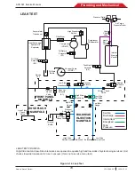
TANK FILL
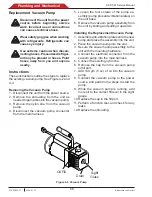
During the tank fill process, the source tank is connected to the low-side service hose and the Recover solenoid S1
is activated. The low-side ball valve is opened and the recover solenoid is cycled to maintain 2.4 bar (35psi) in the
accumulator. When the ISV reaches the target weight, the recover solenoid closes. The low-side ball valve is closed
and the low-side service hose is removed from the source tank.
Figure 4-6. Tank Fill Diagram
Heat Exchanger/
System Oil
Separator
Filter/Dryer
Compressor
(COMP)
Compressor
Oil Separator
Oil Return
Solenoid
(S7)
Oil Drain
Solenoid
(S6)
Accumulator
Transducer
FRONT PANEL
MANIFOLD
HOSE FLUSH
MANIFOLD
BULKHEAD
INJECTION
MANIFOLD
Charge
Solenoid
(S3)
Charge Check
Valve
Low Side
Ball Valve
High Side
Ball Valve
Recover
Check
Valve
Recover
Solenoid
(S1)
Low Side
Transducer
Oil Drain
Bottle
High Side
Gauge
Low Side
Gauge
Vacuum
Solenoid
(S2)
High Pressure
Switch
Vacuum Pump
(PUMP)
High Side
Service Hose
Low Side
Service Hose
HS
Bulkhead
LS
Bulkhead
Hose Flush
Check
Valve
Pressure Relief
Air Purge
Pressure Relief
Internal
Storage
Vessel
Vapor
Check
Valve
Tank Liquid
Solenoid
(S4)
Oil Inject
Bottle
Oil Inject
Solenoid (S5)
Oil Inject
Check Valve
Service
Port
Liquid
Ball
Valve
Suction
Discharge
Intermittent
Energized
Tank
Pressure
TANK FILL
Summary of Contents for ACS 561
Page 1: ...ACS 561 en Repair instruction A C Service Unit ...
Page 95: ......