


ACS 561 Service Manual
Robert Bosch GmbH
SP00D00517
2018-07-11
51
Electrical
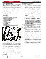
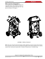
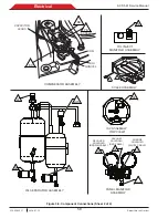
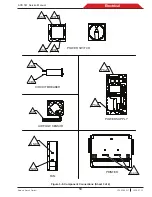
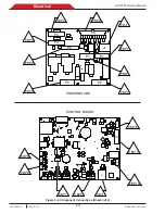
Figure 3-4. Electrical Connections (Sheet 2 of 3)
LOW-SIDE
PRESSURE
TRANSDUCER
(LST)
ACCUMULATOR
(AT)
PRESSURE
TRANSDUCER
P4
AIRFLOW
SENSOR
(AF)
P5
PRINTER
ASSEMBLY
P2
1
1
P15
J3
P18
P3
J1
P8
P10
P9
P2
BT1
P19
LS1
+
-
P17
P12
J2
P16
P13
P4
P5
P6
+
P14
P1
_
JTAG
P11
P7
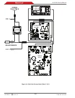
CONTROL
BOARD
P3
P1
P1
ASSEMBLY
SCALE
P3
P1
P2
P4
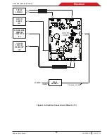
Component Lead
Wire Braid
O
GND2
Summary of Contents for ACS 561
Page 1: ...ACS 561 en Repair instruction A C Service Unit ...
Page 95: ......