


ACS 561 Service Manual
Robert Bosch GmbH
SP00D00517
2018-07-11
68
Plumbing and Mechanical
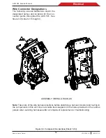
NOTE: All wires must be clear of moving parts, pinch points, and sharp edges.
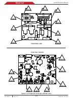
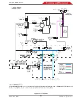
Figure 4-4. Assembly Component Names
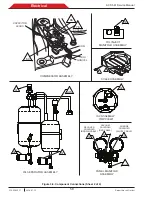
OIL SEPARATOR ASSEMBLY
S6
S7
COMPRESSOR
OIL
SEPARATOR
SYSTEM OIL
SEPARATOR
FILTER DRYER
HPS
HIGH PRESSURE
SWITCH (HPS)
ACCUMULATOR
TRANSDUCER (AT)
OIL DRAIN
SOLENOID
(BLUE CABLE)
COMPRESSOR OIL
RETURN SOLENOID
(VIOLET CABLE)
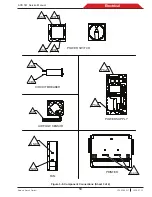
PANEL MANIFOLD ASSEMBLY
S1
S2
S3
HIGH-SIDE
GAUGE
SCHRADER
CORE VALVE
RECOVER
SOLENOID
(BROWN CABLE)
CHARGE CHECK
VALVE
LOW-SIDE
TRANSDUCER (LST)
RECOVER
CHECK VALVE
CHARGE
SOLENOID
(WHITE CABLE)
LOW-SIDE
GAUGE
VACUUM
SOLENOID
(RED CABLE)
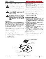
BULKHEAD OIL
INJECT BLOCK
S5
OIL INJECT
SOLENOID
(RED CABLE)
Summary of Contents for ACS 561
Page 1: ...ACS 561 en Repair instruction A C Service Unit ...
Page 95: ......