15
DuraSweeper
®
Parts & Assemblies
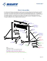
The following illustrations and diagrams detail the parts and assemblies of the DuraSweeper
®
by Bluff.
Some pieces are welded together and are considered a single part. Weldments are not considered
wear parts, so damage to any weldment should be reported to Bluff Manufacturing or a Bluff Distributor
immediately. Repairs to weldments will be subject to the judgment of the Bluff engineering team,
and not all weldments can or should be repaired due to safety concerns or feasibility. In such cases,
complete replacement of the weldment will be necessary.
PARTS LIST
TITLE
PART NUMBER
QTY
ITEM
Assy - Base Module
DS-BS-MOD
1
1
Horizontal Beam/Hoist Assembly
DS180-003
1
1.1
Weld - Beam
DS180-002
1
1.1.1
Beam
DS180-002-001
1
1.1.1.1
Bracket
DS180-002-002
1
1.1.1.2
End Plate
DS180-002-004
2
1.1.1.3
Plate, Cross Brace
DS180-002-006
2
1.1.1.4
Plate, Cable Support
DS180-004-001-015
2
1.1.1.5
Weld - Spool
DS180-003-001
1
1.1.2
Shaft Washer
DS180-003-001-003
2
1.1.2.1
Spool Pipe
DS180-003-001-004
8
1.1.2.2
Hoist, Drive Shaft
DS180-003-001-005
1
1.1.2.3
Bolt Stackup
DS180-BS-4
4
1.1.3
Hoist Shaft Spacer
DS180-003-002
1
1.1.4
Bolt Stackup
DS180-BS-18
4
1.1.5
Hoist Package, Key
DS180-003-004
1
1.1.6
Gearbox Drive
DS180-003-005
1
1.1.7
Shaft Collar
SHAFTCOL200
2
1.1.8
Bearing
BRINGMNT4B200
1
1.1.9
Hoist Shaft Spacer
DS180-003-006
1
1.1.10
Base Beam Assy
DS180-007
2
1.2
Brush Carriage Assy
DS180-004
1
1.3
Column Brace
DS180-008
2
1.4
Cable
DS180-009-001
1
1.5
Assy - Cable, Take-up
DS180-BS-7
1
1.6
Column Assy
DS180-016
2
1.7
Bracket
DS180-004-001-025
1
1.8
Assy - Carriage Guide Bracket
DS180-004-007
2
1.9
Bolt Stackup
DS180-BS-4
4
1.10
Bolt Stackup
DS180-BS-14
4
1.11
Bolt Stackup
DS180-BS-1
34
1.12
Assy - Cable, Static
DS180-BS-8
1
1.13
Prox Switch Bracket
DS180-030-001
1
1.14
Rep - Energy Chain Loop
2
1
1.15
Rep - Wire Rope 2
1
1.16
Prox Switch - Cable Set
PROXSWTCHCS15
1
1.17
Proximity Switch
PROXSWTCH40
1
1.18
Energy Chain, Mounting Bracket, Female
NRGYCHN13MB
1
1.19
Energy Chain, Mounting Bracket, Male
Rep - Energy Chain,
4556T66, Male
1
1.20
Energy Chain
NRGYCHN13LNK
64
1.21
Assy - Anchor Package: Permanent
DS180-PERM
1
2
Base Anchor Bracket Assy
DS180-017
4
2.1
Bolt Stackup
DS180-BS-1
16
2.2
Wedge Anchor Kit
F34512WA
24
2.3
Shim
DS-PERM-001
8
2.4
Assy - Control Package
DS-E10
1
3
Assy - Drive Package
DS-D10
1
4
Assy - Drive Package
DS-D15
1
5
Assy - Drive Package
DS-D20
1
6
Electrical Panel
DS-E20
1
7
Utility vehicle 14.8 m3 color White
utility_white
1
8
Assy - Anchor Package: Portable
DS-PORT
1
9
Jack Assy
DS180-022
4
9.1
Ecology Block Platform
DS180-013
2
9.2
Bolt Stackup
DS180-BS-1
36
9.3
Jack Caster Shoe
DS180-027-001
2
9.4
Ecology Block
6
10
Prox Switch Bracket, Lower
DS180-036-001
2
11
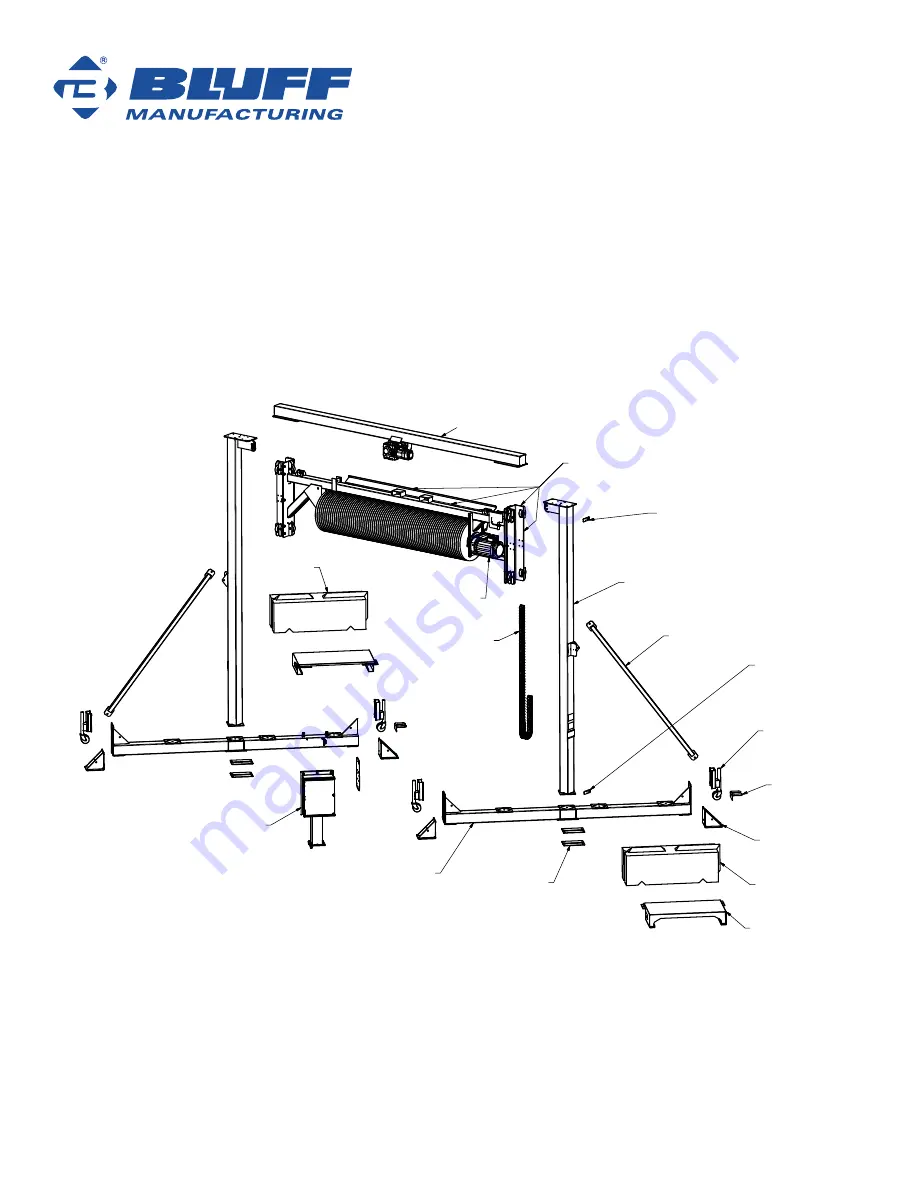
Illustration for Parts and Assemblies Page
file locations:
model - C:\Users\stevebales\Desktop\DuraSweeperManual\Inventor Model 5\Layout.iam
persentation file - C:\Users\stevebales\Desktop\DuraSweeperManual\Inventor Model 5\DS-MainExplodedView-10HP.ipn
drawing - C:\Users\stevebales\Desktop\DuraSweeperManual\Inventor Model 5\DS-MainExplodedView-10HP.idw
PDF - C:\Users\stevebales\Desktop\DuraSweeperManual\Inventor Model 5\DS-MainExplodedView-10HP.pdf
DS180-003
Horizontal Beam/Hoist Assembly
Ecology Block
*not included
Energy Chain
DS180-022
Jack Assy
4 reqd.
DS180-027-001
Jack Caster Shoe
2 reqd.
Ecology Block
*not included
DS180-013
Ecology Block Platform
2 reqd.
DS180-017
Base Anchor Bracket
4 reqd.
DS-PERM-001
Base Shims
8 reqd.
Notes:
Lifting Cable not shown
Fasteners are not shown. See assembly fasteners list.
Base Package consists of items labeled in BLUE text.
Portable Anchor Package consists of items labeled in RED text.
Permanent Anchor Package consists of items labeled in GREEN text.
DS180-007
Base Beam Assy
2 reqd.
DS180-008
Column Brace
2 reqd.
DS180-016
Column Assy
2 reqd.
DS180-004
Brush Carriage Assy
motor not included
DS-D15 Drive Motor
DS-D20 Drive Motor
DS180-036-001
Prox Switch Bracket
1 upper, 1 lower
(both are identical)
DS180-036-001
Prox Switch Bracket
1 upper, 1 lower
(both are identical)
DS-E10
Electrical Panel
Figure 10

