41
DuraSweeper
®
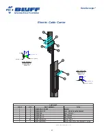
6. Check lifting cables for any damage, corrosion, kinking, broken or cut strands, etc. Replace if any
damage is found.
7. Replace any Safety Labels or decals as necessary.
8. Re-connect power if necessary. All Electrical installation should be done by a certified electrician. If
power re-connection is not needed, skip this step.
Notice: When the main power is re-connected, be sure to observe previous wire connections, so the
motor rotations will be correct.
1. If there’s any doubt that the phasing is correct, do a brush motor rotation test. If the brush motor
turns the wrong direction, switch the main power wiring to reverse motor direction. The unit
should now be wired with the same phasing as the previous (original) installation. This is very
important.
2. Perform the Upper Proximity Test, the Lower Proximity Test, and both Automation Test as
described previously in this manual.
Changing The Brush Wafers
Note: While performing maintenance on the brush assembly, do not leave the weight of the brush
assembly on the brush bristles for more than one hour. If needed, brush assembly can be supported by
the core (axle) on saw horses or similar stable support. Note, brush assembly is 1480 lbs.
1. Lower brush to a comfortable working height.
2. Turn OFF the Power Disconnect switch.
3. Shut down the breaker panel that feeds the DuraSweeper
®
and install a lockout to prevent
accidental energizing.
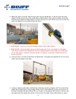
4. Wrap a chain around the upper frame member and around the brush assembly. Chain needs to be
located closer to the “non-motor” side, approximately 1/3 away from the end. This will support the
weight of the brush assembly. (This can be done with an empty pallet on a fork lift). Place the fork
lift and pallet under the brush assembly to hold the weight of the unit.)
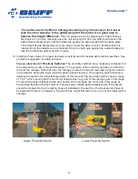
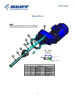
5. Remove the four bolts that hold on the two flange bearings, and lower the unit from the mount plate.
The chain should be supporting the weight of the brush assembly.
6. Remove the bearings and shaft assembly from the brush assembly.
7. Remove the brush plate from the end of the brush assembly.
8. Remove the brush wafers and spacers from the open end of the assembly.
9. The support chain or pallet will have to be moved as you get closer to the motor side in order to
remove all the brush wafers and spacers. Just keep the brush assembly supported at all times.
10. Reverse the steps for placing the new brush wafers and spacers.
11. Once the maintenance of the wafers is completed and the end plate reinstalled, pick up the tube
level with the brush frame.
12. Reinstall the bearings and shaft assembly.

