10
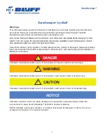
DuraSweeper
®
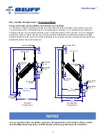
Site Location Requirements - Permanent Model
Please read entire pre-installation manual before proceeding
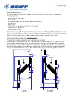
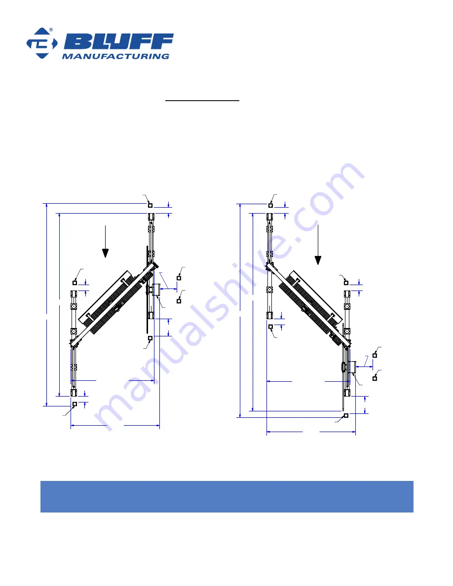
The first step in the pre planning process is to determine the best orientation of the unit for your site.
The orientation of the unit determines the material ejection direction. Unit orientations are defined in
the figures below.
The standard orientation ejects material away from the operator.
The non-standard
orientation, while not ideal, can be used. For permanent units Bluff recommends installing four Bluff
bollards at the entrance and exit to prevent damage from vehicles. We also recommend two additional
bollards to protect the electrical panel.
NOTICE
On a permanent model, orientation cannot be changed without a full reinstall. Please contact
your Bluff Manufacturing dealer or Bluff directly concerning switching unit orientation.
Vehicle Travel
Vehicle Travel
Standard
Configuration
Non-Standard
Configuration
185 in
412 in
this drawing is for
Site Location Requirements - Permanent Model
173 in
base to base
173 in
base to base
model for this drawing:
DS-PermanentStandard
model for this drawing:
DS-PermanentNonStandard
445 in
12 in
approx
12 in
36 in
36 in
12 in
Electric
Panel
Electric
Panel
36 in
12 in
approx
12 in
12 in
381 in
421 in
185 in
36 in
Bluff Bollard SRB42
Bluff Bollard
SRB42
Bluff Bollard
SRB42
Bluff Bollard
SRB42
Bluff Bollard
SRB42
Bluff Bollard
SRB42
Bluff Bollard SRB42
Bluff Bollard
SRB42
Bluff Bollard
SRB42
Bluff Bollard
SRB42
Bluff Bollard
SRB42
Bluff Bollard SRB42

