Revision 15.00 / LB-0028
–
Cerebus Instructions for Use
8
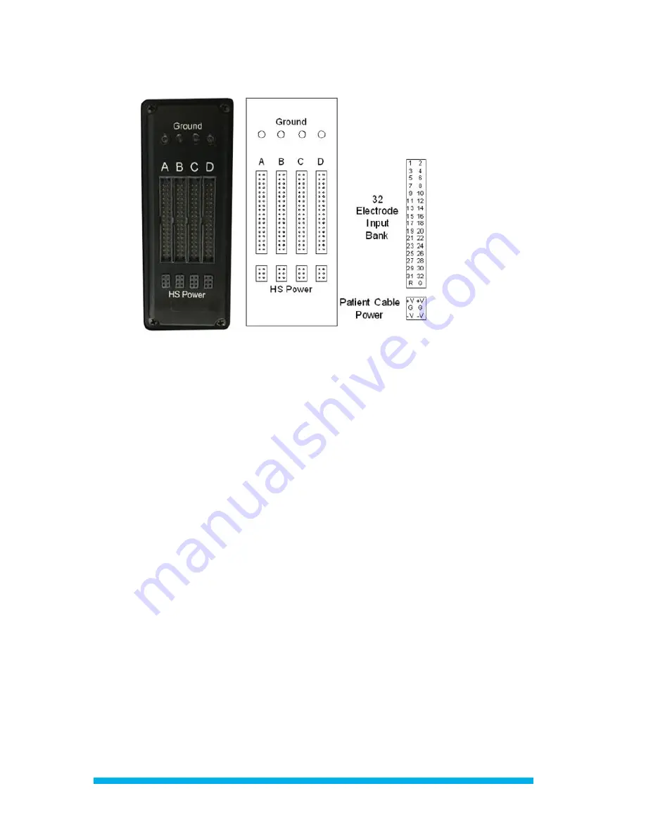
Figure 4- Front End Amplifier front view and pinout
The Amplifier has four 34-pin banks as shown in Figure 4. Each bank consists of 32 channels, a bank
reference pin, and a ground pin. The electrodes within each bank are differentially amplified with respect
to the reference input of the same bank. Connect one reference channel to all banks to use a single
reference for all measurement channels. Four 6-pin Amplifier Power Supply banks provide power (±5V) to
the analog headstages and can deliver up to 130 mA of combined current. The ground pins on every bank
are internally tied together and should be used as the primary experimental ground.
Analog Headstages
Blackrock analog headstages acquire neural signals from electrodes and provide an isolated low-
impedance output to the Front End Amplifier via direct cable connections for each channel. Blackrock
analog headstages ensure maximum common-mode noise rejection by the Front End Amplifier. The high
input impedance and low bias current of the Front End Amplifier inputs make it possible to connect
microelectrodes with 20 k
Ω
(at 1kHz) or lower impedance values directly to the Front End Amplifier
inputs without the need for a headstage. This configuration makes the application more susceptible to
environmental electromagnetic noise.
To minimize environmental noise, it is recommended to keep direct electrode connections shorter than
20 cm (8 inches). For longer connections, headstages from Blackrock Microsystems are recommended.
Headstages allow microelectrodes with impedances up to 5 M
Ω
(at 1kHz), and cables up to 6 feet or 3
meters in length.
Amplifier Power Supply (APS)
The APS consists of five analog and digital supply channels with monitoring, sequencing, and emergency
shutdown controls. The On/Off switch is located on the back of the unit. Once it is switched on, the APS


